



Diesel engines 904.908/914/923/936 of Mercedes Vario (512D-815DA)
.

Removal and installation the engine
Removal 1. Disconnect the negative cable from the battery. 2. Remove the service cover. 3. Remove the split beam. 4. Remove the front engine brackets (on all-wheel drive...
Removal 1. Disconnect the negative cable from the battery. 2. Remove the service cover. 3. Remove the split beam. 4. Remove the front engine brackets (on all-wheel drive...

Intake pipe — removal and installation
Removal 1. Remove compressed air supply pipe 2 (figure 3.2). 2. Disconnect the inlet pipe 1 from the air filter housing 9. 3. Disconnect the intake pipe 1 from the...
Removal 1. Remove compressed air supply pipe 2 (figure 3.2). 2. Disconnect the inlet pipe 1 from the air filter housing 9. 3. Disconnect the intake pipe 1 from the...

Intake manifold — removal and installation
Removal 1. Remove compressed air supply pipe 4 from manifold 1 (figure 3.3). 2. Remove the cylinder head cover. 3. Remove decorative panels 14.1 or 14.2 from manifold...
Removal 1. Remove compressed air supply pipe 4 from manifold 1 (figure 3.3). 2. Remove the cylinder head cover. 3. Remove decorative panels 14.1 or 14.2 from manifold...

Exhaust manifold — removal and installation
Removal 1. Disconnect the negative cable from the battery. 2. Remove the service cover. 3. Remove the gearbox protective cover. 4. Remove shield 13 of the exhaust...
Removal 1. Disconnect the negative cable from the battery. 2. Remove the service cover. 3. Remove the gearbox protective cover. 4. Remove shield 13 of the exhaust...

Cylinder head cover
Removal 1. Remove the service cover. 2. Remove the engine trim panel 7 (figure 3.5). 3. Disconnect the crankcase ventilation pipe 4 from the cylinder head cover 5. 4....
Removal 1. Remove the service cover. 2. Remove the engine trim panel 7 (figure 3.5). 3. Disconnect the crankcase ventilation pipe 4 from the cylinder head cover 5. 4....

Cylinder head
Removal 1. Disconnect the negative cable from the battery. 2. Drain the coolant. 3. Remove the front passenger seat. 4. Remove the exhaust manifold. 5. Remove the fuel...
Removal 1. Disconnect the negative cable from the battery. 2. Drain the coolant. 3. Remove the front passenger seat. 4. Remove the exhaust manifold. 5. Remove the fuel...

Timing Belt Cover — Removal and Installation
Removal 1. Remove starter M1 (figure 3.7). 2. Remove flywheel 10. 3. Remove all fasteners attached to the timing belt cover 2. 4. Remove the crankshaft position sensor...
Removal 1. Remove starter M1 (figure 3.7). 2. Remove flywheel 10. 3. Remove all fasteners attached to the timing belt cover 2. 4. Remove the crankshaft position sensor...

Rocker arms and rocker arm axle
Removal 1. Remove the cylinder head cover 1 (figure 3.8a,b). 2. Remove clamp 3 and rocker arm assembly 4. On engines up to number 039739 3. Remove the double-sided...
Removal 1. Remove the cylinder head cover 1 (figure 3.8a,b). 2. Remove clamp 3 and rocker arm assembly 4. On engines up to number 039739 3. Remove the double-sided...

Camshaft — Removal and Installation
Removal 1. Drain the engine oil. 2. Remove the engine. 3. Remove the rocker arms and rocker arm shaft. 4. Remove the push rods 3 (figure 3.9) 5. Remove the fuel pump. 6....
Removal 1. Drain the engine oil. 2. Remove the engine. 3. Remove the rocker arms and rocker arm shaft. 4. Remove the push rods 3 (figure 3.9) 5. Remove the fuel pump. 6....

Checking valve lift
1. Rotate the crankshaft until the piston of the cylinder being tested is set to the ignition position (TDC). Rocker arms 1 should overlap, both pushrods can rotate, and...
1. Rotate the crankshaft until the piston of the cylinder being tested is set to the ignition position (TDC). Rocker arms 1 should overlap, both pushrods can rotate, and...

Adjusting the thermal clearance of the valves
1. Remove the cylinder head cover. 2. Select the adjustment method (they are described below): Method 1 - Adjustment by the order of cylinder firing; method 2 -...
1. Remove the cylinder head cover. 2. Select the adjustment method (they are described below): Method 1 - Adjustment by the order of cylinder firing; method 2 -...

Valves — removal and installation
Removal 1. Remove the cylinder head 5 (figure 3.12). 2. Remove the injector holders as an assembly. 3. Measure the diameter of the disc B of all valves (engines up to...
Removal 1. Remove the cylinder head 5 (figure 3.12). 2. Remove the injector holders as an assembly. 3. Measure the diameter of the disc B of all valves (engines up to...

Replacing valve seat rings
1. Remove the valves. 2. Secure the cylinder head to the assembly table. 3. Check the inner diameter of the guide bushing using an indicator 4 (figure 3.13). 4. Remove...
1. Remove the valves. 2. Secure the cylinder head to the assembly table. 3. Check the inner diameter of the guide bushing using an indicator 4 (figure 3.13). 4. Remove...

Replacing valve stem seals
1. Remove the cylinder head. 2. Remove the valve springs. 3. Remove the 2 valve stem seals (figure 3.14). 4. Remove the gaskets 4. 5. Lubricate the valve stems 5 and 6...
1. Remove the cylinder head. 2. Remove the valve springs. 3. Remove the 2 valve stem seals (figure 3.14). 4. Remove the gaskets 4. 5. Lubricate the valve stems 5 and 6...
Constant throttle — removal and installation
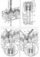
Removal 1. Remove the cylinder head. 2. Remove the injector holder assembly. 3. Remove cover 1 from cylinder head 10 (figure 3.15). Replace sealing ring 2. 4. Insert...
Removal 1. Remove the cylinder head. 2. Remove the injector holder assembly. 3. Remove cover 1 from cylinder head 10 (figure 3.15). Replace sealing ring 2. 4. Insert...
Pistons — Removal and Installation
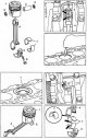
Removal 1. Remove the cylinder head. 2. Remove the tray. 3. Remove the connecting rod cap 5 (figure 3.16a). 4. Remove piston 1 together with connecting rod 4 from the...
Removal 1. Remove the cylinder head. 2. Remove the tray. 3. Remove the connecting rod cap 5 (figure 3.16a). 4. Remove piston 1 together with connecting rod 4 from the...

Piston rings — removal and installation
Removal 1. Remove pistons 4 (figure 3.17). 2. Remove piston rings 1, 2 and 3, starting from the top one. 3. Measure the clearances of piston rings 1 and 2. 4. Measure...
Removal 1. Remove pistons 4 (figure 3.17). 2. Remove piston rings 1, 2 and 3, starting from the top one. 3. Measure the clearances of piston rings 1 and 2. 4. Measure...

Connecting rods — removal, inspection and installation
Removal 1. Remove the pistons. Examination 2. Check the connecting rods for wear. Connecting rods with blue color should be replaced. 3. Check the inner diameter of the...
Removal 1. Remove the pistons. Examination 2. Check the connecting rods for wear. Connecting rods with blue color should be replaced. 3. Check the inner diameter of the...

Crankshaft — removal and installation
Removal 1. Remove the engine. 2. Remove the pistons. 3. Remove the oil pump. 4. Remove the timing belt cover. 5. Remove toothed pulley 8 of the crankshaft (figure...
Removal 1. Remove the engine. 2. Remove the pistons. 3. Remove the oil pump. 4. Remove the timing belt cover. 5. Remove toothed pulley 8 of the crankshaft (figure...

Cylinder block sleeve
Removal 1. Remove the crankshaft. 2. Fix the cylinder block 1 to the boring machine 3 (figure 3.20a). 3. Align the cylinder liner with the boring of the machine 3. 4....
Removal 1. Remove the crankshaft. 2. Fix the cylinder block 1 to the boring machine 3 (figure 3.20a). 3. Align the cylinder liner with the boring of the machine 3. 4....

Crankshaft seals
21.1. Front crankshaft oil seal Removal 1. Remove the groove pulley 1 (figure 3.21a). 2. Secure the puller 3 with three screws (3.2 mm) 4 to the oil seal 2. 3. Remove...
21.1. Front crankshaft oil seal Removal 1. Remove the groove pulley 1 (figure 3.21a). 2. Secure the puller 3 with three screws (3.2 mm) 4 to the oil seal 2. 3. Remove...

Flywheel — removal and installation
Removal 1. Remove the clutch (on cars with manual transmission) or GTR (on cars with automatic transmission). 2. Remove the crankshaft position sensor B15 from the...
Removal 1. Remove the clutch (on cars with manual transmission) or GTR (on cars with automatic transmission). 2. Remove the crankshaft position sensor B15 from the...

Pallet — removal and installation
Removal 1. Remove the double cross beam. 2. Remove the protective cover 7 of the tray 3 (figure 3.23a). 3. Drain the engine oil. 4. Disconnect the wiring connector 8 of...
Removal 1. Remove the double cross beam. 2. Remove the protective cover 7 of the tray 3 (figure 3.23a). 3. Drain the engine oil. 4. Disconnect the wiring connector 8 of...
Oil pump — removal and installation
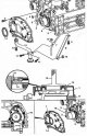
Removal 1. Remove the crankshaft groove pulley. 2. Remove the tray. 3. Remove the oil level indicator tube 7 and the bracket 8 that secures it to the oil intake 12...
Removal 1. Remove the crankshaft groove pulley. 2. Remove the tray. 3. Remove the oil level indicator tube 7 and the bracket 8 that secures it to the oil intake 12...

Oil filter housing
Removal 1. Turn off the ignition and disconnect the negative cable from the battery. 2. Remove the intake pipe. 3. Remove the radiator fan clutch of the cooling system....
Removal 1. Turn off the ignition and disconnect the negative cable from the battery. 2. Remove the intake pipe. 3. Remove the radiator fan clutch of the cooling system....

Oil radiator — removal and installation
Removal 1. Turn off the ignition and disconnect the negative cable from the battery. 2. Remove the service cover. 3. Drain the coolant. 4. Remove shield 9 from the...
Removal 1. Turn off the ignition and disconnect the negative cable from the battery. 2. Remove the service cover. 3. Drain the coolant. 4. Remove shield 9 from the...

Oil level sensor
Removal 1. Drain the engine oil. 2. Disconnect the wiring connector 3; oil level sensor B14 (figure 3.27) 3. Disconnect the oil level sensor wire B14 from the pan 1....
Removal 1. Drain the engine oil. 2. Disconnect the wiring connector 3; oil level sensor B14 (figure 3.27) 3. Disconnect the oil level sensor wire B14 from the pan 1....

Cooling system pump
Removal 1. Remove the radiator. 2. Remove thermostat 4 (figure 3.28a). 3. Remove the fan clutch. 4. Remove the generator drive belt. 5. Remove pulley 15 of cooling...
Removal 1. Remove the radiator. 2. Remove thermostat 4 (figure 3.28a). 3. Remove the fan clutch. 4. Remove the generator drive belt. 5. Remove pulley 15 of cooling...

Thermostat — Removal, Checking and Installation
Removal 1. Drain the coolant. 2. Remove the service cover. 3. Remove the thermostat cover 4 (figure 3.29a). 4. Remove thermostat 2. Figure 3.29a, Removing and installing...
Removal 1. Drain the coolant. 2. Remove the service cover. 3. Remove the thermostat cover 4 (figure 3.29a). 4. Remove thermostat 2. Figure 3.29a, Removing and installing...

Radiator of the cooling system
Removal 1. Drain the coolant. 2. Remove the radiator grille and the decorative panel below the grille. 3. Disconnect the tubes from the air filter housing 3 (figure...
Removal 1. Drain the coolant. 2. Remove the radiator grille and the decorative panel below the grille. 3. Disconnect the tubes from the air filter housing 3 (figure...

Turbocharger — removal and installation
Removal 1. Remove the exhaust manifold 1 together with the turbocharger 2 (figure 3.31). 2. Disconnect the exhaust manifold 1 from the turbocharger 2. 3. Disconnect the...
Removal 1. Remove the exhaust manifold 1 together with the turbocharger 2 (figure 3.31). 2. Disconnect the exhaust manifold 1 from the turbocharger 2. 3. Disconnect the...

Engine Brake Valve
Removal 1. Turn off the ignition and disconnect the negative cable from the battery. 2. Remove the service cover. 3. Remove the gearbox protective cover. 4. Remove...
Removal 1. Turn off the ignition and disconnect the negative cable from the battery. 2. Remove the service cover. 3. Remove the gearbox protective cover. 4. Remove...

Engine control unit
Removal 1. Turn off the ignition. 2. Remove the service cover. 3. Remove engine cover 1 (figure 3.33). 4. Disconnect wiring connectors 3 and 4 from the A6 engine control...
Removal 1. Turn off the ignition. 2. Remove the service cover. 3. Remove engine cover 1 (figure 3.33). 4. Disconnect wiring connectors 3 and 4 from the A6 engine control...

Pump-injector — removal and installation
Removal 1. Turn off the ignition. 2. Remove the fuel line 6 (figure 3.34). 3. Remove the hydraulic pipe mounting bracket from the cylinder head. 4. Wipe the surface near...
Removal 1. Turn off the ignition. 2. Remove the fuel line 6 (figure 3.34). 3. Remove the hydraulic pipe mounting bracket from the cylinder head. 4. Wipe the surface near...

Compressed air pressure sensor (engines 904.908 up to number 040 487)
Removal 1. Remove the service cover. 2. Remove cover 1 from intake manifold 4 (figure 3.35). 3. Disconnect the wiring connector 2 from the compressed air pressure sensor...
Removal 1. Remove the service cover. 2. Remove cover 1 from intake manifold 4 (figure 3.35). 3. Disconnect the wiring connector 2 from the compressed air pressure sensor...

Compressed air temperature sensor (engines 904.908 up to number 040 487)
Removal 1. Remove the service cover. 2. Remove cover 1 from intake manifold 4 (figure 3.36). 3. Disconnect wiring connector 2 from compressed air temperature sensor B9....
Removal 1. Remove the service cover. 2. Remove cover 1 from intake manifold 4 (figure 3.36). 3. Disconnect wiring connector 2 from compressed air temperature sensor B9....

Compressed air temperature/pressure sensor (engines 904.904/908, from number 040488: 904.923/936)
Removal 1. Remove the service cover. 2. Remove cover 1 from the intake manifold (figure 3.37). 3. Disconnect wiring connector 2 from combination sensor 3. 4. Unscrew the...
Removal 1. Remove the service cover. 2. Remove cover 1 from the intake manifold (figure 3.37). 3. Disconnect wiring connector 2 from combination sensor 3. 4. Unscrew the...

Starter — removal, installation
Removal 1. Turn off the ignition and disconnect the negative cable from the battery. 2. Unscrew nuts 3 and remove gaskets 4 (figure 3.38). 3. Lift the rear of the M1...
Removal 1. Turn off the ignition and disconnect the negative cable from the battery. 2. Unscrew nuts 3 and remove gaskets 4 (figure 3.38). 3. Lift the rear of the M1...

Generator — removal and installation
Removal 1. Turn off the ignition and disconnect the negative cable from the battery. 2. Remove the air filter and intake pipe. 3. Remove bracket 13 for fastening the...
Removal 1. Turn off the ignition and disconnect the negative cable from the battery. 2. Remove the air filter and intake pipe. 3. Remove bracket 13 for fastening the...

Diagnostic Trouble Codes for Engines 904.9
Table 3.9. Diagnostic trouble codes for engines 904.9 Fault code Faulty unit 0 10 15 Oil temperature sensor 0 10 16 0 11 15 Fuel temperature sensor 0 11 16 0 12 15...
Table 3.9. Diagnostic trouble codes for engines 904.9 Fault code Faulty unit 0 10 15 Oil temperature sensor 0 10 16 0 11 15 Fuel temperature sensor 0 11 16 0 12 15...
Tightening torques for engine components and parts 904.9
Tightening torques for engine components and parts 904.9 Fastening elements Tightening torques (Nm) Tubes to the compressor 100 Clutch slave cylinder to gearbox 25...
Tightening torques for engine components and parts 904.9 Fastening elements Tightening torques (Nm) Tubes to the compressor 100 Clutch slave cylinder to gearbox 25...
This section is available on: russian, bulgarian, belarusian, ukrainian, serbian, croatian, romanian, polish, slovak, hungarian
More similar sections for repairing other models
☛ Power unit: Engine overhaul car Mercedes 190 (W201) (1982-1993)
☛ Power unit: Engine overhaul car Mercedes W124 (1984-1995)
☛ Power unit: Engine repair car Mercedes W220 (1998-2005)
Link in different formats to this section
TEXTHTMLBB Code
- General information
- Maintenance
- Power unit
- Engines 602.984/985
- Engines 904.908/914/923/936
- Transmission
- Clutch
- Manual gearbox 711.613
- Manual gearbox 710.64/66
- Manual gearbox 715.051
- Automatic gearbox 723.345
- Power take-off box
- Chassis
- Front suspension
- Rear suspension
- Steering
- Brake system
- Body and electrical equipment
- Interior (internal elements)
- Exterior (external elements)
- Heater and air conditioner
- Electrical diagrams
- General information
- User manual
- Maintenance
- Diesel engine OM646
- Engine repair
- Cooling and lubrication system
- Power and exhaust system
- Transmission
- Clutch
- Car gearbox
- Chassis
- Front suspension
- Rear suspension
- Steering
- Brake system
- Body
- Body elements
- Electrical equipment
- Equipment and devices
- Security systems
- Electrical circuits
- General information
- User manual
- Maintenance
- Petrol engines 2.0 l
- Engine repair
- Lubrication system
- Cooling system
- Power and control system
- Petrol engines 2.8 l
- Engine repair
- Lubrication system
- Cooling system
- Power and control system
- Diesel engines 2.3 l
- Engine repair
- Cooling system
- Lubrication system
- Turbocharging and recycling
- Power and control system
- Diesel engines 2.2 l
- Engine repair
- Cooling system
- Lubrication system
- Turbocharging and recycling
- Power and control system
- Transmission
- Clutch
- Mechanical gearbox
- Automatic gearbox
- Chassis
- Front suspension and wheels
- Rear suspension
- Steering
- Brake system
- Body
- Exterior (external elements)
- Interior (internal elements)
- Electrical equipment
- Equipment and devices
- Heater and air conditioner
- Electrical circuits
- General information
- Introduction to the guide
- Maintenance
- Power unit
- Engine repair
- Lubrication system
- Cooling system
- Power and exhaust system
- Transmission
- Clutch
- Mechanical gearbox
- Automatic gearbox
- Front axle
- Rear axle and cardan
- Chassis
- Car suspension
- Steering
- Brake system
- Tires and wheels
- Electrical equipment
- Equipment and devices
- Headlights and lighting
- Power devices
- Electrical circuits