



Vehicle equipment and instruments Mercedes Vito 2 (W639)

Car control system
Modern cars have many systems that must be controlled in a coordinated manner. The complexity of the interaction of various vehicle systems leads to the fact that the...
Modern cars have many systems that must be controlled in a coordinated manner. The complexity of the interaction of various vehicle systems leads to the fact that the...

Operating principle of the CAN multiplex network
The basis for creating a unified control system for Vito Viano vehicles is three multiplex data exchange networks. Operating principle of the CAN multiplex network...
The basis for creating a unified control system for Vito Viano vehicles is three multiplex data exchange networks. Operating principle of the CAN multiplex network...

The principle of signal formation in a multiplex network
VN 9.002 Complex signal in the CAN data bus In normal transmission mode, data packets have the following block configurations (frames) (see figure VN 9.002). The message...
VN 9.002 Complex signal in the CAN data bus In normal transmission mode, data packets have the following block configurations (frames) (see figure VN 9.002). The message...

Block diagram of multiplex networks of Vito Viano cars
To exchange information between the elements of the vehicle's control system, three data transmission systems are used: class B data bus operating in the vehicle's...
To exchange information between the elements of the vehicle's control system, three data transmission systems are used: class B data bus operating in the vehicle's...
List of components of multiplex networks
A1 Instrument cluster A2/6 Multi-disc CD player A2/42 TV receiver A2/56 Radio and navigation unit A6n1 STH system control unit A35/11 SBS system control unit A35/13...
A1 Instrument cluster A2/6 Multi-disc CD player A2/42 TV receiver A2/56 Radio and navigation unit A6n1 STH system control unit A35/11 SBS system control unit A35/13...
Data exchange between data buses
The following control units provide data bus communication. - The control unit for the management information system (N73) is connected to the buses (CAN B) and (CAN C)....
The following control units provide data bus communication. - The control unit for the management information system (N73) is connected to the buses (CAN B) and (CAN C)....
Instrument cluster (A1)
Although the instrument cluster (A1) is connected to both the CAN-B and CAN-C multiplex networks and exchanges information with them, this system is not a gateway. All...
Although the instrument cluster (A1) is connected to both the CAN-B and CAN-C multiplex networks and exchanges information with them, this system is not a gateway. All...

Front universal switching unit
The block is installed in the engine compartment. VN 9.004 The front universal switching unit (NIC) (SAM) is connected to a CAN-B multiplex network. This unit receives...
The block is installed in the engine compartment. VN 9.004 The front universal switching unit (NIC) (SAM) is connected to a CAN-B multiplex network. This unit receives...
SAM Block Functions
The block controls the following functions. Outdoor lighting (ABL). Interior lighting (IBL). Search for and manage lighting devices. Formation of direction indicator...
The block controls the following functions. Outdoor lighting (ABL). Interior lighting (IBL). Search for and manage lighting devices. Formation of direction indicator...
Engine management system
Engines of the OM611 and OM 612 family are high-speed engines with direct injection of diesel fuel into the cylinders, which are equipped with various types of...
Engines of the OM611 and OM 612 family are high-speed engines with direct injection of diesel fuel into the cylinders, which are equipped with various types of...
Functions performed by the control system in different modes
The CDI system performs a number of functions that make up the powertrain control process. Function of fuel supply to the high-pressure fuel pump. The fuel injection...
The CDI system performs a number of functions that make up the powertrain control process. Function of fuel supply to the high-pressure fuel pump. The fuel injection...
Control of fuel supply to the injection pump
Fuel is supplied by a fuel pump located in the measuring and receiving unit (MSU) of the fuel tank. Power is supplied to the pump from the CDI control unit via the fuel...
Fuel is supplied by a fuel pump located in the measuring and receiving unit (MSU) of the fuel tank. Power is supplied to the pump from the CDI control unit via the fuel...
Controlling the amount of fuel injected
In a direct injection system using a fuel injection pump (CDI), controlling the amount of fuel injected is more important than in previous fuel injection technologies....
In a direct injection system using a fuel injection pump (CDI), controlling the amount of fuel injected is more important than in previous fuel injection technologies....
Fuel injection pressure control
The pressure in the high pressure fuel pump is regulated by means of a valve (Y74), to which a pulse signal is supplied (on-off) signal from the CDI control unit. The...
The pressure in the high pressure fuel pump is regulated by means of a valve (Y74), to which a pulse signal is supplied (on-off) signal from the CDI control unit. The...
Controlling the amount of fuel injected during engine start-up
Fuel supply in starting mode does not depend on the position of the accelerator pedal. The starting mode is determined by the CDI system based on a coolant temperature...
Fuel supply in starting mode does not depend on the position of the accelerator pedal. The starting mode is determined by the CDI system based on a coolant temperature...
Injection control in driving mode
The main task of the CDI system in this mode is to provide the required engine torque value, which is set by the position of the accelerator pedal. To do this, the block...
The main task of the CDI system in this mode is to provide the required engine torque value, which is set by the position of the accelerator pedal. To do this, the block...
Idle injection control
The engine idle speed is maintained at approximately 600 rpm. In this mode, the block receives the following information. Message from the unit (N73) about whether the...
The engine idle speed is maintained at approximately 600 rpm. In this mode, the block receives the following information. Message from the unit (N73) about whether the...
Fuel pre — injection control function
Pre-injection is activated in cases where the amount of fuel calculated for injection in a given cycle is large (enough to divide the cycle into several stages). This...
Pre-injection is activated in cases where the amount of fuel calculated for injection in a given cycle is large (enough to divide the cycle into several stages). This...
Main fuel injection control function
The main injection is the second stage of injection in the presence of a pilot injection. Cases of absence of preliminary injection are described above. When calculating...
The main injection is the second stage of injection in the presence of a pilot injection. Cases of absence of preliminary injection are described above. When calculating...
Final stage of injection
The final injection stage is used mainly to reduce the content of solid particles in the exhaust gas. The principle of determining the injection parameters is similar to...
The final injection stage is used mainly to reduce the content of solid particles in the exhaust gas. The principle of determining the injection parameters is similar to...

Glow plug preheating function
The glow plug pre-heating system is designed to achieve the required ignition temperature of the fuel mixture in the cylinder during a cold start. In addition, with...
The glow plug pre-heating system is designed to achieve the required ignition temperature of the fuel mixture in the cylinder during a cold start. In addition, with...

Post-start heating
The post-start heating mode is designed to improve engine starting characteristics, smooth out engine operation during cold starts, and prevent the appearance of blue...
The post-start heating mode is designed to improve engine starting characteristics, smooth out engine operation during cold starts, and prevent the appearance of blue...
Boost pressure control function
The boost pressure is determined by the rotation speed of the supercharger turbine. The turbine speed is regulated by signals from the CDL ECU The boost pressure sensor...
The boost pressure is determined by the rotation speed of the supercharger turbine. The turbine speed is regulated by signals from the CDL ECU The boost pressure sensor...
Air-fuel ratio definitions
On vehicles with equipment code (MF4), the air-fuel ratio is also monitored using an oxygen sensor.
On vehicles with equipment code (MF4), the air-fuel ratio is also monitored using an oxygen sensor.
Exhaust Gas Recirculation (EGR) Control
On vehicles with equipment codes (MG4) and (MF8), the CDI system, via the CDI control unit (N3/9) and the vacuum converter (Y31/5), controls the exhaust gas...
On vehicles with equipment codes (MG4) and (MF8), the CDI system, via the CDI control unit (N3/9) and the vacuum converter (Y31/5), controls the exhaust gas...
Air supply cut-off control
On vehicles with equipment code (MF4), the CDI control unit performs the function of activating the inlet air shut-off valve (Y83).
On vehicles with equipment code (MF4), the CDI control unit performs the function of activating the inlet air shut-off valve (Y83).
Air conditioning compressor shutdown control function
In vehicles equipped with automatic air conditioning (assembly code HH9), when the engine speed is less than 2000 rpm and the signal intensity of the accelerator pedal...
In vehicles equipped with automatic air conditioning (assembly code HH9), when the engine speed is less than 2000 rpm and the signal intensity of the accelerator pedal...

Fuel supply system
VN 9.007 1. TKVD; 2. Fuel tank; 3. Fuel filter; 4. Fuel temperature sensor 650; 5. Fuel pump, combined with fuel level sensor IM3/3; 6. Fuel injection pump M41; 7....
VN 9.007 1. TKVD; 2. Fuel tank; 3. Fuel filter; 4. Fuel temperature sensor 650; 5. Fuel pump, combined with fuel level sensor IM3/3; 6. Fuel injection pump M41; 7....

Functional diagram of engine control
The CDI control unit analyzes the system status based on a set of signals received from the system sensors. Below is a diagram showing the signals coming to the control...
The CDI control unit analyzes the system status based on a set of signals received from the system sensors. Below is a diagram showing the signals coming to the control...
Elements of the engine management system
Electronic control unit. Electronic control unit (ECU). Multiplexed CAN network C. Sensors Crankshaft position sensor. Camshaft position sensor. Incoming air mass...
Electronic control unit. Electronic control unit (ECU). Multiplexed CAN network C. Sensors Crankshaft position sensor. Camshaft position sensor. Incoming air mass...
Electronic Control Unit (ECU)
The CDI control unit (N3/9) controls the following functions. Fuel supply. Control of glow plugs when starting the engine and while driving. Controlling the amount of...
The CDI control unit (N3/9) controls the following functions. Fuel supply. Control of glow plugs when starting the engine and while driving. Controlling the amount of...

Accelerator pedal position sensor (B37)
Purpose Registration of the accelerator pedal position and transmission of information to the engine control unit. Design The accelerator pedal position sensor contains...
Purpose Registration of the accelerator pedal position and transmission of information to the engine control unit. Design The accelerator pedal position sensor contains...

Crankshaft Position Sensor (L5)
Purpose Determining the position of the crankshaft at a given moment in time and transmitting a signal to the engine control unit. Placement and arrangement The...
Purpose Determining the position of the crankshaft at a given moment in time and transmitting a signal to the engine control unit. Placement and arrangement The...

Camshaft Position Sensor (B6/1)
Purpose Contactless determination of the camshaft position. Functioning VN 9.013 RPM signals (synchronization) engine; OT1. TDC 1st cylinder; OT2. TDC 2nd cylinder; OTDC...
Purpose Contactless determination of the camshaft position. Functioning VN 9.013 RPM signals (synchronization) engine; OT1. TDC 1st cylinder; OT2. TDC 2nd cylinder; OTDC...

Coolant temperature sensor (B11/4)
Purpose Detection of coolant temperature and signal transmission to the engine control unit. Accommodation VN 9.016 1. Pressure sensor in the high-pressure fuel pump...
Purpose Detection of coolant temperature and signal transmission to the engine control unit. Accommodation VN 9.016 1. Pressure sensor in the high-pressure fuel pump...

Fuel temperature sensor (B50)
Purpose The fuel temperature sensor (B50) is located in the high-pressure fuel pump (M41). If the fuel temperature is too high, the pressure in the high-pressure fuel...
Purpose The fuel temperature sensor (B50) is located in the high-pressure fuel pump (M41). If the fuel temperature is too high, the pressure in the high-pressure fuel...

Inlet air mass sensor (B2/5), combined with inlet air temperature sensor (B2/5b1)
VN 9.020 1. Incoming air mass sensor B2/5 Purpose The incoming air mass and temperature sensor is designed to send a signal to the engine control unit about the quantity...
VN 9.020 1. Incoming air mass sensor B2/5 Purpose The incoming air mass and temperature sensor is designed to send a signal to the engine control unit about the quantity...

Discharge air temperature sensor (B17/9)
VN 9.023 1. Blown air temperature sensor B17/9 Purpose Determination of the charge air temperature and transmission of a signal to the engine control unit. Design VN...
VN 9.023 1. Blown air temperature sensor B17/9 Purpose Determination of the charge air temperature and transmission of a signal to the engine control unit. Design VN...
Boost pressure sensor (B5/1)
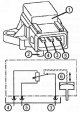
Purpose Detection of air pressure in the intake manifold and transmission of a signal to the engine control unit (N3/9). Design The boost pressure sensor contains...
Purpose Detection of air pressure in the intake manifold and transmission of a signal to the engine control unit (N3/9). Design The boost pressure sensor contains...

Fuel pressure sensor in the high pressure fuel system (B4/6)
VN 9.027 1. High pressure pipe supplying fuel to the high pressure fuel pump; 2. TKVD; 3. High pressure fuel pipes delivering fuel from the high pressure fuel pump to...
VN 9.027 1. High pressure pipe supplying fuel to the high pressure fuel pump; 2. TKVD; 3. High pressure fuel pipes delivering fuel from the high pressure fuel pump to...
Oil condition sensor (B40)
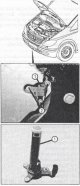
Purpose The oil condition sensor is designed to monitor the temperature, level and degree of contamination of the oil. If the oil level drops too low, a signal is...
Purpose The oil condition sensor is designed to monitor the temperature, level and degree of contamination of the oil. If the oil level drops too low, a signal is...

Input oxygen sensor on the EGR converter (G3/2)
The oxygen sensor is designed to analyze exhaust gases in order to determine the actual air/fuel ratio and correct the composition of the fuel mixture in the cylinders....
The oxygen sensor is designed to analyze exhaust gases in order to determine the actual air/fuel ratio and correct the composition of the fuel mixture in the cylinders....

Air filter outlet pressure sensor (B28/5)
The air filter outlet pressure sensor (B28/5) measures the specified pressure and transmits a signal to the CDI control unit (N3/9). If the vacuum at the air filter...
The air filter outlet pressure sensor (B28/5) measures the specified pressure and transmits a signal to the CDI control unit (N3/9). If the vacuum at the air filter...
CDI control system actuators
The following is a description of the control devices of the CDI control system. This description does not include devices described in the sections " Fuel supply system...
The following is a description of the control devices of the CDI control system. This description does not include devices described in the sections " Fuel supply system...

Glow plugs (R9)
The combustion chamber is preheated by glow plugs fed from the output stage of the preheating system. The duration of pre-heating depends on the coolant temperature....
The combustion chamber is preheated by glow plugs fed from the output stage of the preheating system. The duration of pre-heating depends on the coolant temperature....
Pressure regulating valve in the high pressure fuel pump (Y74)
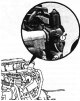
The pressure regulating valve in the high-pressure fuel pump (Y74) together with the fuel supply regulating valve (Y94) maintains the pressure at the level set by the...
The pressure regulating valve in the high-pressure fuel pump (Y74) together with the fuel supply regulating valve (Y94) maintains the pressure at the level set by the...

Exhaust Gas Recirculation (EGR) Valve Actuator
The EGR valve actuator is designed to open and close the EGR valve. This valve regulates the addition of a certain amount of exhaust gas to the incoming air. This is...
The EGR valve actuator is designed to open and close the EGR valve. This valve regulates the addition of a certain amount of exhaust gas to the incoming air. This is...

Exchange Rate Stability System ESP
In a modern car, in particular in Vito Viano cars, a modern system is used to ensure the stability of the car in various situations that arise during movement. This...
In a modern car, in particular in Vito Viano cars, a modern system is used to ensure the stability of the car in various situations that arise during movement. This...
Interaction of systems
The ESP function is the highest priority function among those listed because its action is the most universal. This is expressed in the fact that in order to stabilize...
The ESP function is the highest priority function among those listed because its action is the most universal. This is expressed in the fact that in order to stabilize...

ABS Component Locations (for vehicles not equipped with ESP)
The ESP stability control system was described above. This section describes the elements of the separate ABS system. It should be noted that currently Daimler-Chrysler...
The ESP stability control system was described above. This section describes the elements of the separate ABS system. It should be noted that currently Daimler-Chrysler...

Wheel speed sensors
When the rotor (5) rotates, due to the interaction of magnetic fields in the coil (3), voltage pulses are induced, the repetition frequency of which is rigidly connected...
When the rotor (5) rotates, due to the interaction of magnetic fields in the coil (3), voltage pulses are induced, the repetition frequency of which is rigidly connected...

Lateral acceleration sensor
The acceleration sensor (B24/2) contains an electronic microcircuit (a) for registering the signal. The measurement principle of the acceleration sensor is based on the...
The acceleration sensor (B24/2) contains an electronic microcircuit (a) for registering the signal. The measurement principle of the acceleration sensor is based on the...

Angular velocity (yaw)sensor
Hollow steel cylinder (sensitive element, b) under the influence of piezoelectric elements it begins to vibrate at a certain frequency. 4 pairs of piezoelectric elements...
Hollow steel cylinder (sensitive element, b) under the influence of piezoelectric elements it begins to vibrate at a certain frequency. 4 pairs of piezoelectric elements...

Steering wheel angle sensor
The steering wheel angle sensor (B24/8) is located on the steering column. The sensor signal is proportional to the steering wheel angle. This signal is used to...
The steering wheel angle sensor (B24/8) is located on the steering column. The sensor signal is proportional to the steering wheel angle. This signal is used to...

Hydraulic brake force control unit
VN 9.059 5a. Right front wheel brake mechanism; 5b. Left front wheel brake mechanism; 6a. Right rear wheel brake mechanism; 6b. Left rear wheel brake mechanism; 7. Check...
VN 9.059 5a. Right front wheel brake mechanism; 5b. Left front wheel brake mechanism; 6a. Right rear wheel brake mechanism; 6b. Left rear wheel brake mechanism; 7. Check...

Functioning of the ESP system
ESP system control mode VN 9.060 f. High pressure; g. Pre-pressure The ESP control unit performs brake control action to regulate the vehicle's driving stability. At the...
ESP system control mode VN 9.060 f. High pressure; g. Pre-pressure The ESP control unit performs brake control action to regulate the vehicle's driving stability. At the...

Brake Assist System (BAS): Functional Description
Simulator studies with regular drivers and on a test track have shown that most drivers, in the event of emergency braking, first of all, at the beginning of the braking...
Simulator studies with regular drivers and on a test track have shown that most drivers, in the event of emergency braking, first of all, at the beginning of the braking...

Vehicle Maintenance and Condition Monitoring System (ASSYST)
This system monitors the timeliness of vehicle maintenance both in terms of time intervals and the distance traveled between maintenance visits, depending on the vehicle...
This system monitors the timeliness of vehicle maintenance both in terms of time intervals and the distance traveled between maintenance visits, depending on the vehicle...

Tire pressure monitoring system
The tire pressure monitoring system is designed for operational monitoring for traffic safety purposes. Control can be performed either at the driver's request or in the...
The tire pressure monitoring system is designed for operational monitoring for traffic safety purposes. Control can be performed either at the driver's request or in the...
This section is available on: russian, bulgarian, belarusian, ukrainian, serbian, croatian, romanian, polish, slovak, hungarian
More similar sections for repairing other models
☛ Electrical equipment: Equipment and devices car Mercedes W168 (1997-2004)
☛ Electrical equipment: Equipment and devices car Mercedes W202 (1993-2000)
☛ Electrical equipment: Equipment and devices car Mercedes W123 (1976-1985)
☛ Electrical equipment: Equipment and devices car Mercedes W463 (1999-2019)
☛ Electrical equipment: Equipment and devices car Mercedes W163 (1997-2005)
☛ Electrical equipment: Equipment and devices car Mercedes W140 (1991-1998)
Link in different formats to this section
TEXTHTMLBB Code
- General information
- Maintenance
- Power unit
- Engines 602.984/985
- Engines 904.908/914/923/936
- Transmission
- Clutch
- Manual gearbox 711.613
- Manual gearbox 710.64/66
- Manual gearbox 715.051
- Automatic gearbox 723.345
- Power take-off box
- Chassis
- Front suspension
- Rear suspension
- Steering
- Brake system
- Body and electrical equipment
- Interior (internal elements)
- Exterior (external elements)
- Heater and air conditioner
- Electrical diagrams
- General information
- User manual
- Maintenance
- Diesel engine OM646
- Engine repair
- Cooling and lubrication system
- Power and exhaust system
- Transmission
- Clutch
- Car gearbox
- Chassis
- Front suspension
- Rear suspension
- Steering
- Brake system
- Body
- Body elements
- Electrical equipment
- Equipment and devices
- Security systems
- Electrical circuits
- General information
- User manual
- Maintenance
- Petrol engines 2.0 l
- Engine repair
- Lubrication system
- Cooling system
- Power and control system
- Petrol engines 2.8 l
- Engine repair
- Lubrication system
- Cooling system
- Power and control system
- Diesel engines 2.3 l
- Engine repair
- Cooling system
- Lubrication system
- Turbocharging and recycling
- Power and control system
- Diesel engines 2.2 l
- Engine repair
- Cooling system
- Lubrication system
- Turbocharging and recycling
- Power and control system
- Transmission
- Clutch
- Mechanical gearbox
- Automatic gearbox
- Chassis
- Front suspension and wheels
- Rear suspension
- Steering
- Brake system
- Body
- Exterior (external elements)
- Interior (internal elements)
- Electrical equipment
- Equipment and devices
- Heater and air conditioner
- Electrical circuits
- General information
- Introduction to the guide
- Maintenance
- Power unit
- Engine repair
- Lubrication system
- Cooling system
- Power and exhaust system
- Transmission
- Clutch
- Mechanical gearbox
- Automatic gearbox
- Front axle
- Rear axle and cardan
- Chassis
- Car suspension
- Steering
- Brake system
- Tires and wheels
- Electrical equipment
- Equipment and devices
- Headlights and lighting
- Power devices
- Electrical circuits