



Repair of a gasoline engine 2.8 l car Mercedes Vito 1

Removal the engine with the subframe
Removal 1. Disconnect the negative cable from the battery. 2. Drain the coolant. 3. Remove the front wheels. 4. Disconnect the air conditioner pipes. 5. Remove the side...
Removal 1. Disconnect the negative cable from the battery. 2. Drain the coolant. 3. Remove the front wheels. 4. Disconnect the air conditioner pipes. 5. Remove the side...

Removal the engine with transmission
Removal 1. Remove the engine together with the subframe. 2. Drain the fluid from the steering gear. 3. Disconnect from the refrigerant pressure sensor B61 (see figure...
Removal 1. Remove the engine together with the subframe. 2. Drain the fluid from the steering gear. 3. Disconnect from the refrigerant pressure sensor B61 (see figure...

Air filter
Removal 1. Loosen clamps 1 securing air flow sensor 2 to filter housing 3 (see figure 3.7). Figure 3.7. Air filter: 1. Clamp, 2. Air flow sensor, 3. Air filter, 4....
Removal 1. Loosen clamps 1 securing air flow sensor 2 to filter housing 3 (see figure 3.7). Figure 3.7. Air filter: 1. Clamp, 2. Air flow sensor, 3. Air filter, 4....

Cylinder head cover
Removal 1. Remove the intake manifold 1 (see figure 3.8). Figure 3.8. Cylinder head cover: 1. Intake manifold, 2. Cylinder head cover, 3. Nut, 4. Bolt, 5. Cylinder head,...
Removal 1. Remove the intake manifold 1 (see figure 3.8). Figure 3.8. Cylinder head cover: 1. Intake manifold, 2. Cylinder head cover, 3. Nut, 4. Bolt, 5. Cylinder head,...

Intake manifold
Removal 1. Disconnect the negative cable from the battery. 2. Remove the radiator 1 (see figure 3.9). Figure 3.9. Intake manifold: 1. Radiator, 2. Air flow sensor, 3....
Removal 1. Disconnect the negative cable from the battery. 2. Remove the radiator 1 (see figure 3.9). Figure 3.9. Intake manifold: 1. Radiator, 2. Air flow sensor, 3....

Exhaust manifold
Removal 1. Remove the mass air flow sensor. 2. Unscrew nuts 1 securing heat shield 2 to exhaust manifold 3 (see figure 3.10). Figure 3.10. Exhaust manifold: 1, 5. Nuts,...
Removal 1. Remove the mass air flow sensor. 2. Unscrew nuts 1 securing heat shield 2 to exhaust manifold 3 (see figure 3.10). Figure 3.10. Exhaust manifold: 1, 5. Nuts,...

Exhaust gas system
Removal 1. Remove clamp 1 securing the rear part of the exhaust system 2 to the front part 3 (see figure 3.11). Figure 3.11. Exhaust system: 1, 5. Clamps, 2. Rear part...
Removal 1. Remove clamp 1 securing the rear part of the exhaust system 2 to the front part 3 (see figure 3.11). Figure 3.11. Exhaust system: 1, 5. Clamps, 2. Rear part...

Cylinder head
Removal 1. Disconnect the negative cable from the battery. 2. Remove the cylinder head cover 3 (see figure 3.12). Figure 3.12. Cylinder head: 1. Intake manifold, 2....
Removal 1. Disconnect the negative cable from the battery. 2. Remove the cylinder head cover 3 (see figure 3.12). Figure 3.12. Cylinder head: 1. Intake manifold, 2....

Upper timing belt cover
Removal 1. Remove the cylinder head cover 2. 2. Remove ignition coil 3 together with high-voltage wires (see figure 3.15). Figure 3.15. Upper timing belt cover: 1....
Removal 1. Remove the cylinder head cover 2. 2. Remove ignition coil 3 together with high-voltage wires (see figure 3.15). Figure 3.15. Upper timing belt cover: 1....

Lower timing belt cover
Removal 1. Remove the automatic transmission. 2. Remove the upper timing belt cover 1 (see figure 3.16). Figure 3.16. Lower timing belt cover: 1. Upper timing belt...
Removal 1. Remove the automatic transmission. 2. Remove the upper timing belt cover 1 (see figure 3.16). Figure 3.16. Lower timing belt cover: 1. Upper timing belt...

Chain tensioner
Removal 1. Remove the EGR valve 1 (see figure 3.17). Figure 3.17. Chain tensioner: 1. Exhaust gas recirculation valve, 2. Chain tensioner. 2. Remove chain tensioner 2...
Removal 1. Remove the EGR valve 1 (see figure 3.17). Figure 3.17. Chain tensioner: 1. Exhaust gas recirculation valve, 2. Chain tensioner. 2. Remove chain tensioner 2...

Replacing the drive chain
1. Remove the lower timing belt cover 2 (see figure 3.18). Figure 3.18. Replacing the drive chain: 1. Camshafts, 2. Lower timing belt cover, 3. Intermediate shaft...
1. Remove the lower timing belt cover 2 (see figure 3.18). Figure 3.18. Replacing the drive chain: 1. Camshafts, 2. Lower timing belt cover, 3. Intermediate shaft...

Checking the basic position of the camshafts
1. Remove the cylinder head cover 1 (see figure 3.19). Figure 3.19. Checking the basic position of the camshafts: 1. Cylinder head cover, 2. Groove pulley of the...
1. Remove the cylinder head cover 1 (see figure 3.19). Figure 3.19. Checking the basic position of the camshafts: 1. Cylinder head cover, 2. Groove pulley of the...

Camshafts
Removal 1. Remove the cylinder head cover 1 (see figure 3.20). Figure 3.20. Camshafts: 1. Cylinder head cover, 2. Upper timing belt cover, 3. Camshafts, 4. Bolt, 5....
Removal 1. Remove the cylinder head cover 1 (see figure 3.20). Figure 3.20. Camshafts: 1. Cylinder head cover, 2. Upper timing belt cover, 3. Camshafts, 4. Bolt, 5....
Valves — removal and installation
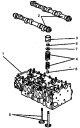
Removal 1. Remove the cylinder head 1 (see figure 3.21). Figure 3.21. Valves: 1. Cylinder head, 2. Camshafts, 3. Hydraulic compensator, 4. Valve spring, 5. Valves, 6....
Removal 1. Remove the cylinder head 1 (see figure 3.21). Figure 3.21. Valves: 1. Cylinder head, 2. Camshafts, 3. Hydraulic compensator, 4. Valve spring, 5. Valves, 6....
Replacing valve seals
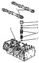
Removal 1. Remove the camshafts 1 (see figure 3.22). Figure 3.22. Replacing valve seals: 1. Camshafts, 2. Spark plug hole, 3. Hydraulic compensator, 4. Valve spring, 5....
Removal 1. Remove the camshafts 1 (see figure 3.22). Figure 3.22. Replacing valve seals: 1. Camshafts, 2. Spark plug hole, 3. Hydraulic compensator, 4. Valve spring, 5....

Crankshaft Groove Pulley
Removal 1. Remove the alternator drive belt 1 (see figure 3.23). Figure 3.23. Crankshaft groove pulley: 1. Generator drive belt, 2. Groove pulley of the crankshaft, 3....
Removal 1. Remove the alternator drive belt 1 (see figure 3.23). Figure 3.23. Crankshaft groove pulley: 1. Generator drive belt, 2. Groove pulley of the crankshaft, 3....

Replacing the front crankshaft oil seal
Removal 1. Remove the crankshaft groove pulley 1 (see figure 3.24). Figure 3.24. Replacing the front crankshaft oil seal: 1. Groove pulley of the crankshaft, 2. Front...
Removal 1. Remove the crankshaft groove pulley 1 (see figure 3.24). Figure 3.24. Replacing the front crankshaft oil seal: 1. Groove pulley of the crankshaft, 2. Front...

Replacing the rear crankshaft oil seal
Removal 1. Remove the drive disc 1 (see figure 3.25). Figure 3.25. Replacing the rear crankshaft oil seal: 1. Leading disk, 2. Rear oil seal, 3. Crankshaft. 2. Remove...
Removal 1. Remove the drive disc 1 (see figure 3.25). Figure 3.25. Replacing the rear crankshaft oil seal: 1. Leading disk, 2. Rear oil seal, 3. Crankshaft. 2. Remove...

Flywheel / drive disk
Removal 1. Remove the automatic transmission. 2. Unscrew bolts 1 securing drive disk 2 to crankshaft 3 (see figure 3.26). Figure 3.26. Flywheel/drive disk: 1. Bolt, 2....
Removal 1. Remove the automatic transmission. 2. Unscrew bolts 1 securing drive disk 2 to crankshaft 3 (see figure 3.26). Figure 3.26. Flywheel/drive disk: 1. Bolt, 2....
This section is available on: russian, bulgarian, belarusian, ukrainian, serbian, croatian, romanian, polish, slovak, hungarian
More similar sections for repairing other models
☛ Power unit: Engine overhaul car Mercedes 190 (W201) (1982-1993)
☛ Power unit: Engine overhaul car Mercedes W124 (1984-1995)
☛ Power unit: Engine repair car Mercedes W220 (1998-2005)
Link in different formats to this section
TEXTHTMLBB Code
- General information
- Maintenance
- Power unit
- Engines 602.984/985
- Engines 904.908/914/923/936
- Transmission
- Clutch
- Manual gearbox 711.613
- Manual gearbox 710.64/66
- Manual gearbox 715.051
- Automatic gearbox 723.345
- Power take-off box
- Chassis
- Front suspension
- Rear suspension
- Steering
- Brake system
- Body and electrical equipment
- Interior (internal elements)
- Exterior (external elements)
- Heater and air conditioner
- Electrical diagrams
- General information
- User manual
- Maintenance
- Diesel engine OM646
- Engine repair
- Cooling and lubrication system
- Power and exhaust system
- Transmission
- Clutch
- Car gearbox
- Chassis
- Front suspension
- Rear suspension
- Steering
- Brake system
- Body
- Body elements
- Electrical equipment
- Equipment and devices
- Security systems
- Electrical circuits
- General information
- User manual
- Maintenance
- Petrol engines 2.0 l
- Engine repair
- Lubrication system
- Cooling system
- Power and control system
- Petrol engines 2.8 l
- Engine repair
- Lubrication system
- Cooling system
- Power and control system
- Diesel engines 2.3 l
- Engine repair
- Cooling system
- Lubrication system
- Turbocharging and recycling
- Power and control system
- Diesel engines 2.2 l
- Engine repair
- Cooling system
- Lubrication system
- Turbocharging and recycling
- Power and control system
- Transmission
- Clutch
- Mechanical gearbox
- Automatic gearbox
- Chassis
- Front suspension and wheels
- Rear suspension
- Steering
- Brake system
- Body
- Exterior (external elements)
- Interior (internal elements)
- Electrical equipment
- Equipment and devices
- Heater and air conditioner
- Electrical circuits
- General information
- Introduction to the guide
- Maintenance
- Power unit
- Engine repair
- Lubrication system
- Cooling system
- Power and exhaust system
- Transmission
- Clutch
- Mechanical gearbox
- Automatic gearbox
- Front axle
- Rear axle and cardan
- Chassis
- Car suspension
- Steering
- Brake system
- Tires and wheels
- Electrical equipment
- Equipment and devices
- Headlights and lighting
- Power devices
- Electrical circuits