



Car gearbox Mercedes Vito 2 (W639)

Gearbox designation and technical characteristics
The basic layout of the car is classic, with a longitudinal engine placement in a block with a gearbox and rear-wheel drive. All-wheel drive versions of the vehicle are...
The basic layout of the car is classic, with a longitudinal engine placement in a block with a gearbox and rear-wheel drive. All-wheel drive versions of the vehicle are...

Rear axle final drive gearbox
The main transmission gearbox is mounted on the vehicle body and connected to the wheels by means of swinging drive shafts and constant velocity joints (hereinafter...
The main transmission gearbox is mounted on the vehicle body and connected to the wheels by means of swinging drive shafts and constant velocity joints (hereinafter...

Manual transmission type 716.6
The new 716.6 manual transmission is a fully synchronized twin-shaft gearbox with six forward gears and one reverse gear. VN 4.002: 1 Primary shaft; 2. Main shaft; 3....
The new 716.6 manual transmission is a fully synchronized twin-shaft gearbox with six forward gears and one reverse gear. VN 4.002: 1 Primary shaft; 2. Main shaft; 3....
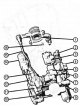
Hydraulic control unit
Mechanical gearboxes of type 716.6 can be equipped with either mechanical cable control or semi-automatic hydraulic control. In the second case, the gearbox is equipped...
Mechanical gearboxes of type 716.6 can be equipped with either mechanical cable control or semi-automatic hydraulic control. In the second case, the gearbox is equipped...

Mechanical gear shifting
The gear shift mechanism using a cable drive is unified with a semi-automatic mechanism. The difference is that the forces to the internal elements of the gearshift...
The gear shift mechanism using a cable drive is unified with a semi-automatic mechanism. The difference is that the forces to the internal elements of the gearshift...

Disassembly and assembly of the semi-automatic gearbox 716.6
Preparatory operations 1. Disconnect the hydraulic pump connector. 2. Turn on the ignition and shift gears throughout the entire range until the pressure in the gear...
Preparatory operations 1. Disconnect the hydraulic pump connector. 2. Turn on the ignition and shift gears throughout the entire range until the pressure in the gear...

Disassembly and assembly of the front part of the gearbox housing
VN 4.026 Disassembly and assembly of the front part of the gearbox housing 1. Gear shift mechanism main shaft bearing; 2. Gearbox primary shaft bearing; 3. Intermediate...
VN 4.026 Disassembly and assembly of the front part of the gearbox housing 1. Gear shift mechanism main shaft bearing; 2. Gearbox primary shaft bearing; 3. Intermediate...

Clutch release mechanism position sensor
VN 4.027 Clutch release mechanism 1. Position sensor; 2. Screws
VN 4.027 Clutch release mechanism 1. Position sensor; 2. Screws

Pressure sensor in the hydraulic drive of the gearbox control
VN 4.028 Pressure sensor in the hydraulic drive of the gearbox control 1. Pressure sensor connector; 2. Pressure sensor
VN 4.028 Pressure sensor in the hydraulic drive of the gearbox control 1. Pressure sensor connector; 2. Pressure sensor
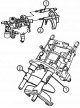
Internal gear shift mechanism
VN 4.029 Gear shift mechanism 1. Reverse gear engagement fork; 2. Fork for engaging 1st and 2nd gears
VN 4.029 Gear shift mechanism 1. Reverse gear engagement fork; 2. Fork for engaging 1st and 2nd gears
Mechanical elements of the gearbox
Synchronizers Transmissions Synchronizers for manual transmission type NSG 250, installed on vehicles with equipment code MC1 (engine OM646,65 kW (88 hp) at 3800 rpm)...
Synchronizers Transmissions Synchronizers for manual transmission type NSG 250, installed on vehicles with equipment code MC1 (engine OM646,65 kW (88 hp) at 3800 rpm)...

Three-cone synchronizing mechanism
Three-cone synchronizing mechanism The three-cone synchronizer mechanism for gear engagement is used in the SG-S 370 and SG-S 400 versions. An additional conical ring...
Three-cone synchronizing mechanism The three-cone synchronizer mechanism for gear engagement is used in the SG-S 370 and SG-S 400 versions. An additional conical ring...
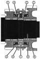
Double cone synchronizing mechanism
The double-cone synchronising gear engagement mechanism is used in the SG-S 250 and SG-S 270 versions to engage gears 1 through 4, and in the SG-S 370 and SG-S 400...
The double-cone synchronising gear engagement mechanism is used in the SG-S 250 and SG-S 270 versions to engage gears 1 through 4, and in the SG-S 370 and SG-S 400...

Single cone synchronizing mechanism
VN 4. 032 Single-cone synchronizing mechanism: 1. Main shaft; 2. Single-cone synchronizer for 5th and 6th gears 3. Single-cone synchronizer for reverse gear VN 4.033...
VN 4. 032 Single-cone synchronizing mechanism: 1. Main shaft; 2. Single-cone synchronizer for 5th and 6th gears 3. Single-cone synchronizer for reverse gear VN 4.033...

Intermediate shaft
VN 4.034 Intermediate shaft assembly: 1. Fixing ring; 2. A gear wheel fixed on a shaft (5th gear); 3. A gear wheel fixed on a shaft (6th gear); 4. Freely rotating 3rd...
VN 4.034 Intermediate shaft assembly: 1. Fixing ring; 2. A gear wheel fixed on a shaft (5th gear); 3. A gear wheel fixed on a shaft (6th gear); 4. Freely rotating 3rd...

Main shaft and primary shaft
VN 4.035 Main shaft and primary shaft: 1. Gear shift clutch; 2. Reverse gear clutch hub; 3. Compression spring; 4. Slider (narrow); 5. Clutch locking ball; 6....
VN 4.035 Main shaft and primary shaft: 1. Gear shift clutch; 2. Reverse gear clutch hub; 3. Compression spring; 4. Slider (narrow); 5. Clutch locking ball; 6....

Components of the rear axle final drive gearbox
VN 4.036 1. Lid; 2. Screw M10x35 mm; 3. Protective ring; 4. Sealing ring; 5. Gearbox housing; 6. Right overlay; 7. Sealing ring; 8. Flange; 9. Nut; 10. Branch pipe; 11....
VN 4.036 1. Lid; 2. Screw M10x35 mm; 3. Protective ring; 4. Sealing ring; 5. Gearbox housing; 6. Right overlay; 7. Sealing ring; 8. Flange; 9. Nut; 10. Branch pipe; 11....

Removal and installation the rear final drive
VN 4.037 Fastening of the rear axle final drive gearbox: 1. Rear crossmember for gearbox mounting; 2. Screw for fastening the crossmember to the body; 3. Screw for...
VN 4.037 Fastening of the rear axle final drive gearbox: 1. Rear crossmember for gearbox mounting; 2. Screw for fastening the crossmember to the body; 3. Screw for...

Removal and installation the propeller shaft
1. Remove the propeller shaft by following these steps. 2. Disconnect the front section of the propeller shaft (1) from the gearbox (only for vehicles without all-wheel...
1. Remove the propeller shaft by following these steps. 2. Disconnect the front section of the propeller shaft (1) from the gearbox (only for vehicles without all-wheel...
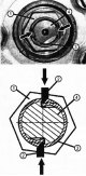
Removal and installation rear axle drive shafts
1. Apply the parking brake. 2. Lower the rear axle of the vehicle (only for vehicles with air springs on the rear suspension(cLO equipment code). 3. Set the level...
1. Apply the parking brake. 2. Lower the rear axle of the vehicle (only for vehicles with air springs on the rear suspension(cLO equipment code). 3. Set the level...
Removal the inner CV joint of the drive shaft from the rear axle final drive gearbox
1. Remove the CV joint (1) from the gearbox (2) using a mounting blade as shown in Figure VN 4.043. VN 4.043 Shown using the example of the left rear axle drive shaft 1....
1. Remove the CV joint (1) from the gearbox (2) using a mounting blade as shown in Figure VN 4.043. VN 4.043 Shown using the example of the left rear axle drive shaft 1....

Removal the outer CV joint from the drive shaft
Removal 1. Clamp the shaft in a vice using a protective pad. 2. Remove the CV joint (1) using a hammer and a 32 mm open-end wrench. VN 4.045 Installation 4. Press the CV...
Removal 1. Clamp the shaft in a vice using a protective pad. 2. Remove the CV joint (1) using a hammer and a 32 mm open-end wrench. VN 4.045 Installation 4. Press the CV...

Removal the inner CV joint from the drive shaft
Removal 1. To remove the CV joint, loosen the retaining ring (4) (the projections of the retaining ring are shown by arrows) and at the same time remove the CV joint,...
Removal 1. To remove the CV joint, loosen the retaining ring (4) (the projections of the retaining ring are shown by arrows) and at the same time remove the CV joint,...

Replacing the CV joint boot
Removal 1. Disconnect the clamps (1) and (2) using special pliers (3) (drawing VN 4.049). 2. Remove the inner (6) and outer (7) CV joint boots (drawing VN 4.050). 4.049...
Removal 1. Disconnect the clamps (1) and (2) using special pliers (3) (drawing VN 4.049). 2. Remove the inner (6) and outer (7) CV joint boots (drawing VN 4.050). 4.049...

Front axle gearbox
VN 4.051 1. Main gear; 2. Sealing ring; 3. Threaded plug; 4. Threaded plug; 5. Support (looks more like a rubber bushing); 6. Drive shaft; 7. Drive shaft; 8. Bushing; 9....
VN 4.051 1. Main gear; 2. Sealing ring; 3. Threaded plug; 4. Threaded plug; 5. Support (looks more like a rubber bushing); 6. Drive shaft; 7. Drive shaft; 8. Bushing; 9....
This section is available on: russian, bulgarian, belarusian, ukrainian, serbian, croatian, romanian, polish, slovak, hungarian
More similar sections for repairing other models
☛ Transmission: Transmission car Mercedes W168 (1997-2004)
☛ Transmission: Car gearbox car Mercedes W202 (1993-2000)
☛ Transmission: Mechanical gearbox car Mercedes W124 (1984-1995)
☛ Transmission: Mechanical gearbox car Mercedes W163 (1997-2005)
☛ Transmission: Mechanical gearbox car Mercedes W126 (1979-1991, petrol)
Link in different formats to this section
TEXTHTMLBB Code
- General information
- Maintenance
- Power unit
- Engines 602.984/985
- Engines 904.908/914/923/936
- Transmission
- Clutch
- Manual gearbox 711.613
- Manual gearbox 710.64/66
- Manual gearbox 715.051
- Automatic gearbox 723.345
- Power take-off box
- Chassis
- Front suspension
- Rear suspension
- Steering
- Brake system
- Body and electrical equipment
- Interior (internal elements)
- Exterior (external elements)
- Heater and air conditioner
- Electrical diagrams
- General information
- User manual
- Maintenance
- Diesel engine OM646
- Engine repair
- Cooling and lubrication system
- Power and exhaust system
- Transmission
- Clutch
- Car gearbox
- Chassis
- Front suspension
- Rear suspension
- Steering
- Brake system
- Body
- Body elements
- Electrical equipment
- Equipment and devices
- Security systems
- Electrical circuits
- General information
- User manual
- Maintenance
- Petrol engines 2.0 l
- Engine repair
- Lubrication system
- Cooling system
- Power and control system
- Petrol engines 2.8 l
- Engine repair
- Lubrication system
- Cooling system
- Power and control system
- Diesel engines 2.3 l
- Engine repair
- Cooling system
- Lubrication system
- Turbocharging and recycling
- Power and control system
- Diesel engines 2.2 l
- Engine repair
- Cooling system
- Lubrication system
- Turbocharging and recycling
- Power and control system
- Transmission
- Clutch
- Mechanical gearbox
- Automatic gearbox
- Chassis
- Front suspension and wheels
- Rear suspension
- Steering
- Brake system
- Body
- Exterior (external elements)
- Interior (internal elements)
- Electrical equipment
- Equipment and devices
- Heater and air conditioner
- Electrical circuits
- General information
- Introduction to the guide
- Maintenance
- Power unit
- Engine repair
- Lubrication system
- Cooling system
- Power and exhaust system
- Transmission
- Clutch
- Mechanical gearbox
- Automatic gearbox
- Front axle
- Rear axle and cardan
- Chassis
- Car suspension
- Steering
- Brake system
- Tires and wheels
- Electrical equipment
- Equipment and devices
- Headlights and lighting
- Power devices
- Electrical circuits