



2. Lower the rear axle of the vehicle (only for vehicles with air springs on the rear suspension(cLO equipment code).
3. Set the level control lever to passive mode (only for vehicles with rear air springs(cLO equipment code).
4. Remove the rear hub protective cap.
5. Unscrew the central nut securing the drive shaft in the rear hub, for which perform the following steps.
Removal the nut
5.1. Bend back the parts of the collar concave for fixing the nut (shown by arrows in the figure VN 4.041) and unscrew the nut (1). When unscrewing the nut, the wheel must be on the ground. It is not allowed to move the vehicle with the nuts (1) loosened.
Installing and tightening the nut
(Material taken from a web resource: «MERCEDESMAN»)
5.2. Tightening of the nut is performed in two stages according to the scheme: 165 Nm + 60°
Caution: Always use a new nut for installation.
Fixing the nut
5.3. Using a suitable tool, press the collar (3) of the nut (1) into the grooves of the splined end (4) of the outer CV joint. The locking (concave) part of the collar must fit tightly against the surface of the groove.
5.4. Apply a control mark on the nut and on the splined tip using paint.
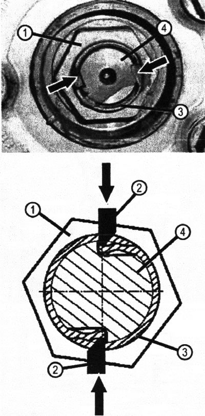
VN 4.041 1. Nut; 2. Nut locking device; 3. Nut collar; 4. Splined tip of the outer CV joint
6. Release the parking brake.
7. Remove the wheel.
8. Remove the rear axle final drive gearbox.
9. Using a mounting blade, remove the inner CV joint of the drive shaft (1) from the final drive gearbox (for details, see. below).
10. Remove the outer CV joint from the rear arm hub (3).
11. Perform installation in reverse order.
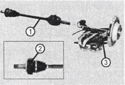
VN 4.042 1. Rear wheel drive shaft; 2. Additional weight of the drive shaft (for cars with OM646 engine, code MC1 or MC2); 3. Rear suspension arm