



2.2L Diesel Engine Management System Mercedes Vito 1

Electronic Fuel Injection Control Unit CDI
The CDI control unit controls the following systems based on signals received from control units and sensors: fuel supply; amount of fuel injected; exhaust gas toxicity...
The CDI control unit controls the following systems based on signals received from control units and sensors: fuel supply; amount of fuel injected; exhaust gas toxicity...

Fuel injection system coolant temperature sensor CD1
Removal 1. Disconnect the compressed air supply pipe from the mixing chamber 1 (see figure 5.56). Figure 5.56. CDI fuel injection system coolant temperature sensor: 1....
Removal 1. Disconnect the compressed air supply pipe from the mixing chamber 1 (see figure 5.56). Figure 5.56. CDI fuel injection system coolant temperature sensor: 1....

Air flow meter
Removal 1. Disconnect the wiring connector from the B39 flow meter (see figure 5.57). Figure 5.57. Air flow meter: 1. Clamp, 2. Air intake pipe, 3. Bolt, 4. Air filter...
Removal 1. Disconnect the wiring connector from the B39 flow meter (see figure 5.57). Figure 5.57. Air flow meter: 1. Clamp, 2. Air intake pipe, 3. Bolt, 4. Air filter...

High pressure fuel pump intermediate gear
Removal 1. Disconnect the negative cable from the battery. 2. Remove the Y20-Y23 injectors (see figure 5.58). Figure 5.58. High pressure fuel pump intermediate gear: 1....
Removal 1. Disconnect the negative cable from the battery. 2. Remove the Y20-Y23 injectors (see figure 5.58). Figure 5.58. High pressure fuel pump intermediate gear: 1....

High pressure fuel pump
Removal 1. Turn off the ignition. 2. Remove the vacuum pump. 3. Disconnect the wiring connector from the Y73 shut-off valve (see figure 5.59). Figure 5.59. High pressure...
Removal 1. Turn off the ignition. 2. Remove the vacuum pump. 3. Disconnect the wiring connector from the Y73 shut-off valve (see figure 5.59). Figure 5.59. High pressure...

Vacuum pump
Removal 1. Remove the upper engine bracket 6 (see figure 5.60). Figure 5.60. Vacuum pump: 1. Vacuum tube, 2. Vacuum pump, 3. Dog, 4. Bolt, 5. Sealing ring, 6. Engine...
Removal 1. Remove the upper engine bracket 6 (see figure 5.60). Figure 5.60. Vacuum pump: 1. Vacuum tube, 2. Vacuum pump, 3. Dog, 4. Bolt, 5. Sealing ring, 6. Engine...

Fuel cut-off valve
Removal 1. Disconnect the wiring connector 1 from the Y75 shut-off valve (see figure 5.61). Figure 5.61. Fuel cut-off valve: 1. Wiring connector, 2. Fuel injection line,...
Removal 1. Disconnect the wiring connector 1 from the Y75 shut-off valve (see figure 5.61). Figure 5.61. Fuel cut-off valve: 1. Wiring connector, 2. Fuel injection line,...

Fuel pressure sensor in the distributor
Removal 1. Remove the fuel filter 1 (see figure 5.62). Figure 5.62. Fuel pressure sensor in the distributor: 1. Fuel filter, 2. Wiring connector, 3. Distributor, B66....
Removal 1. Remove the fuel filter 1 (see figure 5.62). Figure 5.62. Fuel pressure sensor in the distributor: 1. Fuel filter, 2. Wiring connector, 3. Distributor, B66....

Fuel pressure regulating valve
Removal 1. Disconnect wiring connector 1 from the fuel pressure regulating valve. 2. Remove the fuel pressure regulating valve Y74 (see figure 5.63). Figure 5.63. Fuel...
Removal 1. Disconnect wiring connector 1 from the fuel pressure regulating valve. 2. Remove the fuel pressure regulating valve Y74 (see figure 5.63). Figure 5.63. Fuel...

Fuel distributor
Removal 1. Disconnect the negative cable from the battery. 2. Remove the air filter and mixing chamber with the EGR valve. 3. Remove the decorative panel of the cylinder...
Removal 1. Disconnect the negative cable from the battery. 2. Remove the air filter and mixing chamber with the EGR valve. 3. Remove the decorative panel of the cylinder...
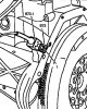
Crankshaft position sensor
Removal 1. Turn off the ignition. 2. Disconnect the wiring connector B73.1 of the crankshaft position sensor (see figure 5.65). Figure 5.65. Crankshaft position sensor:...
Removal 1. Turn off the ignition. 2. Disconnect the wiring connector B73.1 of the crankshaft position sensor (see figure 5.65). Figure 5.65. Crankshaft position sensor:...

Camshaft speed sensor
Removal 1. Remove the decorative panel of the cylinder head cover. 2. Disconnect the wiring connector 1 from the B48 camshaft speed sensor (see figure 5.66). Figure...
Removal 1. Remove the decorative panel of the cylinder head cover. 2. Disconnect the wiring connector 1 from the B48 camshaft speed sensor (see figure 5.66). Figure...

Injectors — removal and installation
Removal 1. Disconnect the negative cable from the battery. 2. Remove the mixing chamber with the EGR valve. 3. Remove the decorative panel of the cylinder head cover 8...
Removal 1. Disconnect the negative cable from the battery. 2. Remove the mixing chamber with the EGR valve. 3. Remove the decorative panel of the cylinder head cover 8...

Glow plugs
Removal 1. Disconnect the negative cable from the battery. 2. Remove the decorative panel of the cylinder head cover 1 (see figure 5.68). Figure 5.68. Glow plugs: 1....
Removal 1. Disconnect the negative cable from the battery. 2. Remove the decorative panel of the cylinder head cover 1 (see figure 5.68). Figure 5.68. Glow plugs: 1....

Pre-heating relay
Removal 1. Disconnect the negative cable from the battery. 2. Disconnect the wiring connector A15.1 and A15.2 (see figure 5.69). Figure 5.69. Pre-heating relay: A15....
Removal 1. Disconnect the negative cable from the battery. 2. Disconnect the wiring connector A15.1 and A15.2 (see figure 5.69). Figure 5.69. Pre-heating relay: A15....

Checking engine compression
1. Warm up the engine to operating temperature of approximately 80°C. 2. Turn off the ignition and remove the key. 3. Remove glow plugs R13-R16 (see figure 5.70). Figure...
1. Warm up the engine to operating temperature of approximately 80°C. 2. Turn off the ignition and remove the key. 3. Remove glow plugs R13-R16 (see figure 5.70). Figure...

Generator — removal and installation
Removal 1. Disconnect the negative cable from the battery. 2. Remove the generator drive belt. 3. Remove the compressed air supply tube. 4. Disconnect the compressed air...
Removal 1. Disconnect the negative cable from the battery. 2. Remove the generator drive belt. 3. Remove the compressed air supply tube. 4. Disconnect the compressed air...

Starter — removal and installation
Removal 1. Disconnect the negative cable from the battery. 2. Unscrew nut 1 securing wire 4 to starter M1 (see figure 5.72). Figure 5.72. Starter: 1, 2. Nut, 3. Bolt, 4....
Removal 1. Disconnect the negative cable from the battery. 2. Unscrew nut 1 securing wire 4 to starter M1 (see figure 5.72). Figure 5.72. Starter: 1, 2. Nut, 3. Bolt, 4....
This section is available on: russian, bulgarian, belarusian, ukrainian, serbian, croatian, romanian, polish, slovak, hungarian
More similar sections for repairing other models
☛ Gasoline engines: Control system car Mercedes W210 (1996-2002)
Link in different formats to this section
TEXTHTMLBB Code
- General information
- Maintenance
- Power unit
- Engines 602.984/985
- Engines 904.908/914/923/936
- Transmission
- Clutch
- Manual gearbox 711.613
- Manual gearbox 710.64/66
- Manual gearbox 715.051
- Automatic gearbox 723.345
- Power take-off box
- Chassis
- Front suspension
- Rear suspension
- Steering
- Brake system
- Body and electrical equipment
- Interior (internal elements)
- Exterior (external elements)
- Heater and air conditioner
- Electrical diagrams
- General information
- User manual
- Maintenance
- Diesel engine OM646
- Engine repair
- Cooling and lubrication system
- Power and exhaust system
- Transmission
- Clutch
- Car gearbox
- Chassis
- Front suspension
- Rear suspension
- Steering
- Brake system
- Body
- Body elements
- Electrical equipment
- Equipment and devices
- Security systems
- Electrical circuits
- General information
- User manual
- Maintenance
- Petrol engines 2.0 l
- Engine repair
- Lubrication system
- Cooling system
- Power and control system
- Petrol engines 2.8 l
- Engine repair
- Lubrication system
- Cooling system
- Power and control system
- Diesel engines 2.3 l
- Engine repair
- Cooling system
- Lubrication system
- Turbocharging and recycling
- Power and control system
- Diesel engines 2.2 l
- Engine repair
- Cooling system
- Lubrication system
- Turbocharging and recycling
- Power and control system
- Transmission
- Clutch
- Mechanical gearbox
- Automatic gearbox
- Chassis
- Front suspension and wheels
- Rear suspension
- Steering
- Brake system
- Body
- Exterior (external elements)
- Interior (internal elements)
- Electrical equipment
- Equipment and devices
- Heater and air conditioner
- Electrical circuits
- General information
- Introduction to the guide
- Maintenance
- Power unit
- Engine repair
- Lubrication system
- Cooling system
- Power and exhaust system
- Transmission
- Clutch
- Mechanical gearbox
- Automatic gearbox
- Front axle
- Rear axle and cardan
- Chassis
- Car suspension
- Steering
- Brake system
- Tires and wheels
- Electrical equipment
- Equipment and devices
- Headlights and lighting
- Power devices
- Electrical circuits