
- fuel supply;
- the amount of injected fuel;
- exhaust gas toxicity reduction system;
- turbocharged;
- cruise control;
- air conditioner compressor.
The CDI control unit checks incoming and outgoing signals, checks the probability and history of the occurrence of a malfunction (see fig. 5.53, 5.54). If a certain signal is not received from the sensor, its value is used in an emergency.
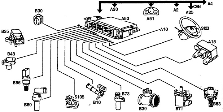
Pic. 5.53. Input signals used by the CDI engine control unit:
A2. ABS/ETS control unit,
A4. ETC control unit,
A10. Airbag/ETR control unit,
A15. glow plugs,
A20. air conditioning control panel,
A25. DAS control unit,
A53. CDI control unit,
AT 10 O'CLOCK. Oil level sensor,
B30. fuel temperature sensor,
B35. boost pressure sensor,
B39. mass air flow meter,
B48. Camshaft Position Sensor,
B60. coolant temperature sensor,
B63. Inlet air temperature sensor,
B66. Fuel pressure sensor in the distributor,
B71. accelerator pedal position sensor,
B73. crankshaft position sensor,
R15. Dashboard,
S105. clutch pedal position sensor,
S123. Cruise control switch.
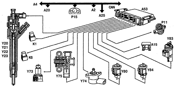
Pic. 5.54. Outgoing signals from the CDI engine control unit:
A2. ABS/ETS control unit,
A4. ETC control unit,
A15. glow plugs,
A20. air conditioning control panel,
A25. DAS control unit,
A53. CDI control unit,
K1. starter relay,
K6. Power relay,
R11. diagnostic socket,
R15. Dashboard,
Y20. Nozzle 1,
Y21. Nozzle 2,
Y22. Nozzle 3,
Y23. Nozzle 4,
Y73. High pressure fuel pump shut-off valve,
Y74. Pressure control valve in the distributor,
Y75. Fuel cut-off valve of the fuel pump,
Y80. Vacuum boost pressure converter,
Y83. shut-off valve,
Y84. Vacuum converter of the EGR system.
CAN bus
The CDI control unit receives variable information from the ABS/ETS control unit, including information from the wheel speed sensors, the brake light switch, and the ABS/ETS system status.
The ETC control unit transmits to the CDI control unit such data as the position of P and N of the gear selector lever of the automatic transmission, the inclusion of a downshift "kickdown", gear engagement, and torque converter lockup status.
The CDI control unit feeds the received information to the instrument panel and air conditioning control panel, including information about the fuel level in the tank, engine shutdown time, pressure and refrigerant, and the operating status of the air conditioning compressor.
Removing
1. Disconnect the negative cable from the battery.
2. Remove the lower right instrument panel cover.
3. Remove the right side deflector 1 (see fig.5.55).
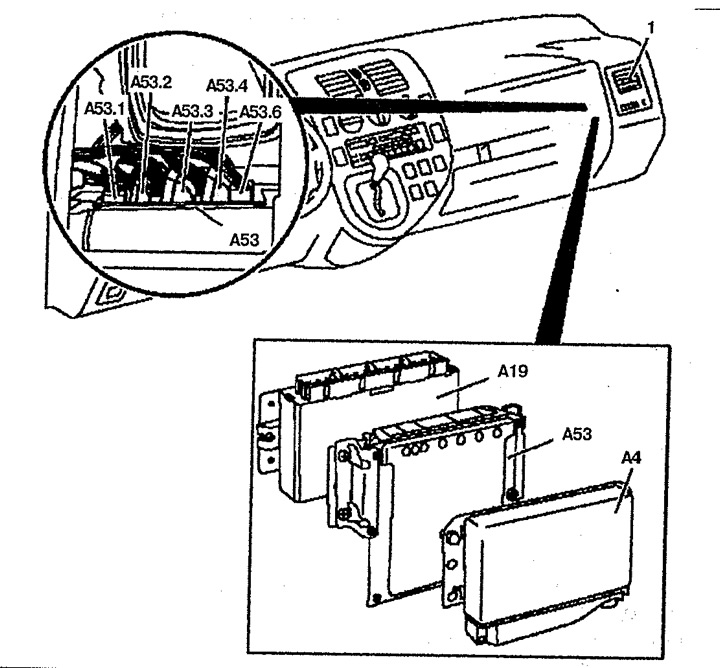
Pic. 5.55. CDI electronic fuel injection control unit:
1. Side deflector,
A19. Control unit for a closed electrical system,
A4. ETC control unit,
A53. CDI control unit,
A53.1. Wiring connector 1 CDI control unit,
A53.2. Wiring connector 2 CDI control units,
A53.3. Wiring connector 3 CDI control units,
A53.4. Wiring connector 4 CDI control units,
A53.5. Wiring connector 5 of the CDI control unit.
4. Disconnect connectors A53.1, A53.2 and A53.3 from the CDI A53 control unit.
5. Disconnect the wiring connector from the ETC A4 control unit.
6. Disconnect the CDI control unit from the bracket. Push the CDI control unit up and remove it from the bracket. The CDI control unit can be installed between the A19 control unit of the closed electrical system and the A4 ETC control unit.
Installation
1. Installation is made in an order, the return to removal.