
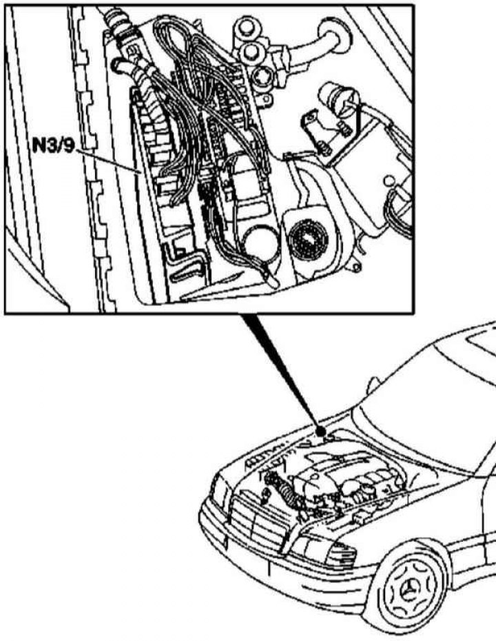
CDI control module installation details (N3/9) on models 163.113 (612 series engine)
1.Injection control module installation details (CDI) on models 163.113 (612 series engine) shown on ref. an illustration to which all references in the text refer.
2. Remove the cover of the mounting block located on the left side of the engine compartment.
3. Disconnect the electrical wiring and remove the control module (N3/9).
4. Installation is carried out in the reverse order - make sure that the connector is securely fixed.
Models 163.128
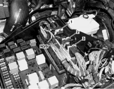
Installation details of the CDI control module on models 163.128 (628 series engine)
1 - Contact connector of the control module; 2 - Contact connector of the control module; 3 - Contact connector of the control module; N3/9 - CDI control module
1.Injection control module installation details (CDI) on models 163.128 (628 series engine) shown in the illustration, which includes all references in the text.
2. Disconnect the negative cable from the battery.
3. Open the hood and lock it in an upright position.
4. Remove the covers from the fuse/relay mounting block.
5. Release the clamps and disconnect the electrical wiring connectors (first 3, then 1 and 2) CDI control module (N3/9).
6. Pull up to remove the control module (N3/9).
7. Installation is carried out in the reverse order - first of all, the connector is connected and fixed (1). Track reliability of fixing of sockets.
8. Finally, clear the memory of the on-board self-diagnosis module (see chapter Engine Electrical Systems).