
Valve assembly installation details on models 163.128 (628 series engine)
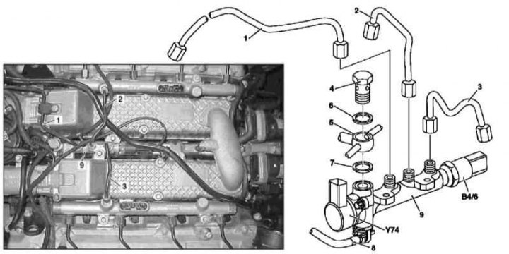
1. Valve assembly installation details on models 163.128 (628 series engine) shown in the illustration, which includes all references in the text.
2. Remove the air distribution pipe (see Section Servicing Air Inlet Components).
3. Remove the fuel filter assembly with support bracket (see chapter Servicing Air Inlet Components).
4. Disconnect the electrical wiring from the pressure sensors in the fuel line (В4/6) and pressure control valve (Y74).
5. Disconnect pressure fuel lines (1, 2 and 3), - Seal open ends of disconnected lines/fittings immediately, collect traces of spilled fuel.
6. Remove the hollow bolt (4) male connector (5).
Attention! O-rings must be replaced without fail!
7. Remove valve block (9) from the distribution pipeline of the air path, having previously disconnected the return line from it (8).
8. Installation is carried out in the reverse order - do not forget to replace the sealing elements (6, 7), start the engine and check the power system components for signs of leaks. In conclusion, clear the memory of the on-board self-diagnosis module (see chapter Engine Electrical Systems).