
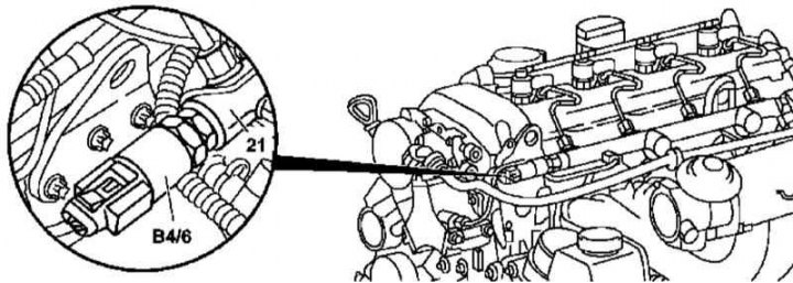
Installation details of the pressure sensor in the fuel distribution line on models 163.113 (612 series engine)
21 - Highway
B4/6 - Pressure sensor
1. Installation details of the fuel rail pressure sensor on models 163.113 (612 series engine) shown in the illustration, which includes all references in the text.
2. Remove panels of finishing of a cover of a head of cylinders.
3. Disconnect the electrical wiring and remove the pressure sensor (В4/6).
4. Installation is carried out in the reverse order. Finally, clear the memory of the on-board self-diagnosis module (see chapter Engine Electrical Systems).
Models 163.128
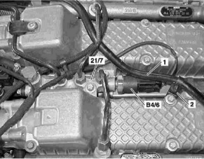
Details of installation of the gauge of pressure in the fuel distributive highway on models 163.128 (628 series engine)
1 - Vacuum line; 2 - Support bracket; 21/7 - Valve block; В4/6 - Pressure sensor
1. Installation details of the fuel rail pressure sensor on models 163.128 (628 series engine) shown in the illustration, which includes all references in the text.
2. Disconnect the air distributor pipe (see Section Servicing Air Inlet Components).
3. Release from the support bracket (2) and lay aside the vacuum line (1).
4. Disconnect the electrical wiring and remove the pressure sensor (В4/6).
5. Installation is carried out in the reverse order. Finally, clear the memory of the on-board self-diagnosis module (see chapter Engine Electrical Systems).