
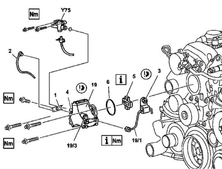
Details of installation of injection pump on models 163.113 (612 series engine)
1 - Support bracket; 2 - Fuel return line; 3 - Pressure line support bracket; 4 - Transition nozzle; 5 - Drive element; 19 - injection pump; 19/1 - High pressure pump pressure line; 19/3 - Threaded fitting; Y75 - Electric shut-off valve
1. Details of installation of injection pump on models 163.113 (612 series engine) shown in the illustration, which includes all references in the text.
2. Remove panels of finishing of a cover of a head of cylinders.
3. Remove the accessory drive belt.
4. Talk away from the injection pump (19) pressure line (19/1).
5. Remove the bracket from the pump assembly (1).
6. Disconnect from injection pump (19) fuel return line (2).
7. Remove the electric shut-off valve (Y75).
8. Remove the fixing bolts and remove the injection pump assembly (19).
Attention! Do not open the injection pump assembly, - if necessary, remove the drive element (5)!
9. Disconnect the connecting pipe from the injection pump (4).
10. Installation is carried out in the reverse order. Do not forget to replace all sealing elements, make sure that the mating surfaces are clean.
Note. The drive element is replaced in a set with an intermediate sprocket of the injection pump drive (see chapter Engine).
Models 163.128
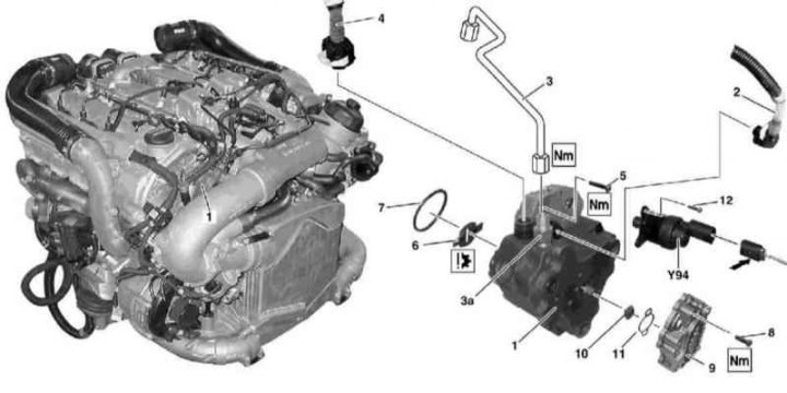
Details of installation of injection pump on models 163.128 (628 series engine)
1 - injection pump; 2 - Fuel supply line; 3 - Pressure line high pressure fuel pump; 3a - Threaded fitting; 4 - Fuel return line; 5 - Bolt; 6 - Floating clutch advancing the angle of injection; 7 - O-ring; 8 - Bolt; 9 - Preliminary fuel pump; 10 - Drive element; 11 - O-ring; 12 - Bolt; Y94 - Mixture quality control valve
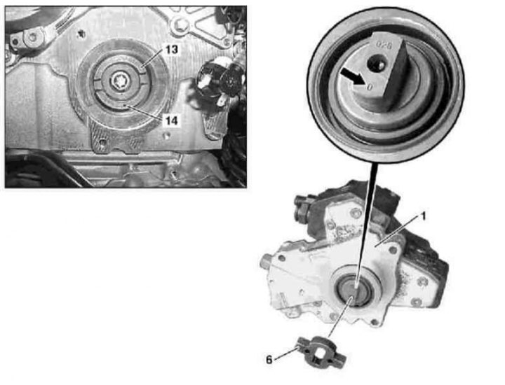
Details of installation of injection pump on models 163.128 (628 series engine)
1 - injection pump; 6 - Floating clutch advancing the angle of injection; 13 - Intermediate sprocket of the injection pump drive with a centrifugal corrector; 14 - Nest
1. Details of installation of injection pump on models 163.128 (628 series engine) shown in the illustrations, which include all references in the text.
2. Remove the throttle positioner with upper air sleeves.
3. Talk away from the injection pump (1) pressure line (3) and fuel return line (4).
4. Disconnect the communication line (arrow) from mixture quality control valve (Y94).
5. Turn out bolts (5) and remove the injection pump assembly (1).
Attention! Do not open the injection pump assembly - if necessary, remove the floating coupling (6)!
6. Assess the degree of wear of the floating clutch (6), replace if necessary.
7. Installation is carried out in the reverse order - make sure that when installing the injection pump, the socket (13) intermediate sprocket has been turned in the same direction as the zero mark (arrow). Don't forget to replace the tensioner seal. Do not forget to replace all sealing elements, make sure that the mating surfaces are clean.