
Models 463.323 (M612)
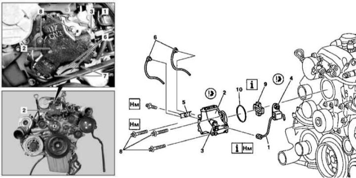
Details of installation of injection pump (M612)
1 - Pressure line; 2 - injection pump; 3 - Threaded fitting; 4, 5 - Brackets; 6 - Fuel return line; 7 - Clamps; 8 - Bolts; 9 - Drive element; 10 - O-ring
1. Remove the cylinder head cover trim panels.
2. Remove the accessory drive belt (see chapter Engine).
3. Talk away from the injection pump (2) pressure line (1), - do not loosen the threaded fitting (3), which should be kept from turning with the second key. Disconnect the bracket from the lifting eye of the power unit (4).
4. Remove from pump assembly (2) bracket (5).
5. Release the fixing straps (7) and move aside the fuel return lines (6).
6. Disconnect return line (6) from injection pump (2), - Prepare to collect spilled fuel.
Note. The sealing ring must be replaced without fail.
7. Turn out bolts (8) and remove the injection pump assembly (2).
Attention! The injection pump is not subject to disassembly! If necessary, the drive element can be removed from it (9) (prepare a replacement o-ring (10).
8. Installation is carried out in the reverse order. Do not forget to replace the sealing elements, ensure that the mating surfaces are clean and that the drive element is properly seated (9).
Note. Worn drive element (9) is replaced in a set with an intermediate sprocket of the injection pump drive.
9. In conclusion, clear the memory of the processor of the on-board self-diagnosis system (see chapter Engine Electrical Systems).
Models 463.333 (M628)
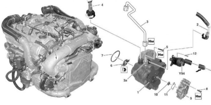
Details of the installation of the high-pressure fuel pump of the M628 engine (1 of 2)
1 - injection pump; 2 - Fuel supply line; 3 - Pressure line high pressure fuel pump; 3a - Threaded fitting; 4 - Fuel return line; 5 - Bolt; 6 - Floating clutch advancing the angle of injection; 7 - O-ring; 8 - Bolt; 9 - Preliminary fuel pump; 10 - Drive element; 11 - O-ring; 12 - Bolt; Y94 - Mixture quality control valve
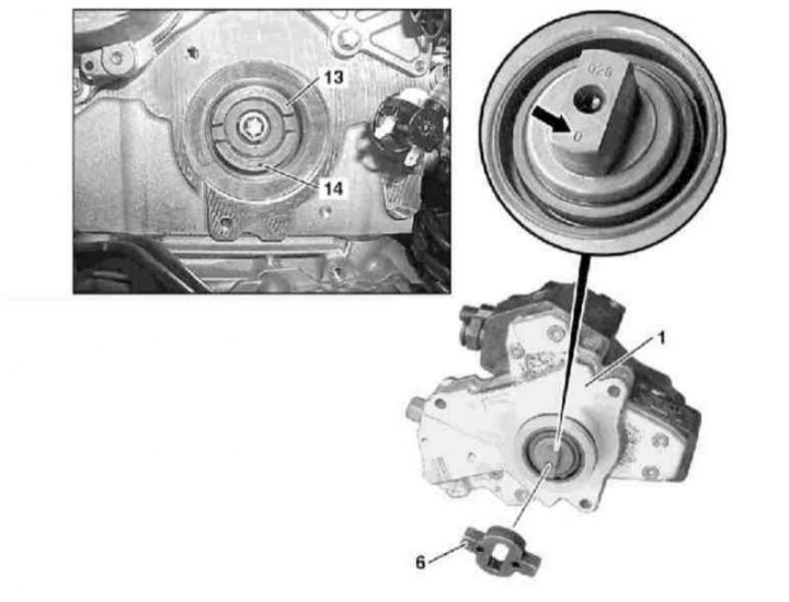
Details of the installation of the high-pressure fuel pump of the M628 engine (2 of 2)
1 - injection pump; 6 - Floating clutch advancing the angle of injection; 13 - Intermediate sprocket of the injection pump drive with a centrifugal corrector; 14 - Nest
1. Remove air cleaner and throttle actuator with top air ducts (see Section Servicing Air Inlet Components).
2. Talk away from the injection pump (1) pressure line (3) and fuel return line (4), - prepare replacement sealing elements (cone and ring).
Note. Threaded fitting (3a) should be kept from turning with a second key.
3. Disconnect the communication line (arrow) from mixture quantity control valve (Y94).
4. Turn out bolts (5) and remove the injection pump assembly (1).
Attention! Do not open the injection pump assembly - if necessary, remove the floating coupling (6)!
5. Assess clutch wear (6), if necessary, replace it (assembled with an intermediate gear of a high pressure fuel pump and a centrifugal corrector (13)).
6. Installation is carried out in the reverse order - make sure that when installing the injection pump, the socket (14) intermediate sprocket has been turned in the same direction as the zero mark (arrow). Don't forget to replace the tensioner seal. Do not forget to replace all sealing elements, make sure that the mating surfaces are clean.
7. In conclusion, clear the memory of the processor of the on-board self-diagnosis system (see chapter Engine Electrical Systems).