
Models 463.323 (M612)
Air cleaner and air filter
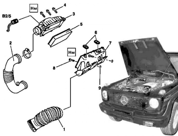
Air cleaner installation details (M612)
Filter element replacement (M612)
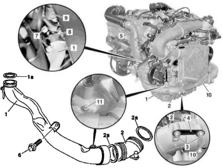
1. Remove the cylinder head cover trim panels.
2. Disconnect the electrical wiring from the hot-wire MAF sensor (B2/5).
3. Remove the air intake (1).
4. Take off the sleeve (2) air intake of the boost path, - if necessary, prepare a replacement mounting clamp.
5. Turn out fixing bolts (4) and remove the top section (cover) (3) air cleaner housing (11).
6. Remove the filter element (5).
7. Remove the rubber o-rings from the cylinder head cover (6), - damaged rings must be replaced.
8. If necessary, turn out the fixing bolts (8) with washers (9) and remove the bottom section (7) air cleaner housing (11).
9. Installation is carried out in the reverse order - before installing the filter element (5) clean the dust valve (10), do not forget to reset the service indicator after replacing the element.
Air intake assembly with air mass sensor (MAF)
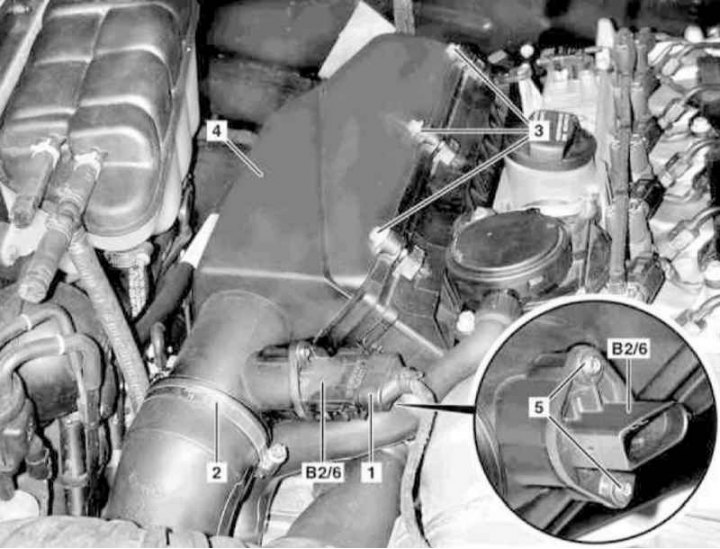
Air intake assembly installation details with MAF sensor (M612)
1. Remove the cylinder head cover trim panels.
2. Disconnect the connector (1) MAF sensor wiring.
3. Detach the sleeve (2), remove the bolts (3) and remove the air cleaner cover (4).
4. Turn out bolts (5) and separate from the lid (4) air cleaner air intake with integrated MAF sensor (B2/6), - check the condition of the sealing ring, if necessary, prepare a replacement element.
5. Installation is carried out in the reverse order.
6. Finally, clear the memory of the on-board self-diagnosis module (see chapter Engine Electrical Systems).
Intake air temperature sensor (IAT)
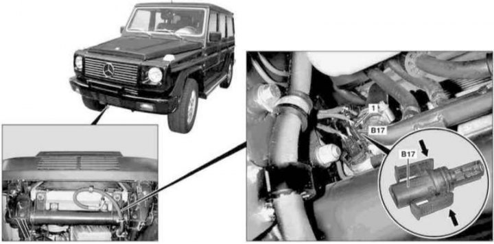
IAT sensor installation details (M612)
1. Remove the crankcase protection.
2. Disconnect the connector (1) IAT sensor wiring (B17).
3. Squeeze the mounting brackets (arrows) and remove the IAT sensor (B17).
Attention! To avoid damage to the mounting brackets, do not remove or install the IAT sensor with the wiring connected - if the brackets are damaged, the sensor must be replaced without fail!
4. Installation is carried out in the reverse order.
5. Finally, clear the memory of the on-board self-diagnosis module (see chapter Engine Electrical Systems).
The air duct of the pressurization path
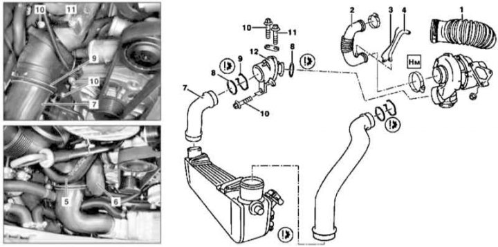
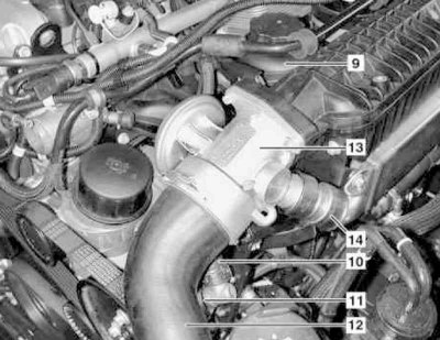
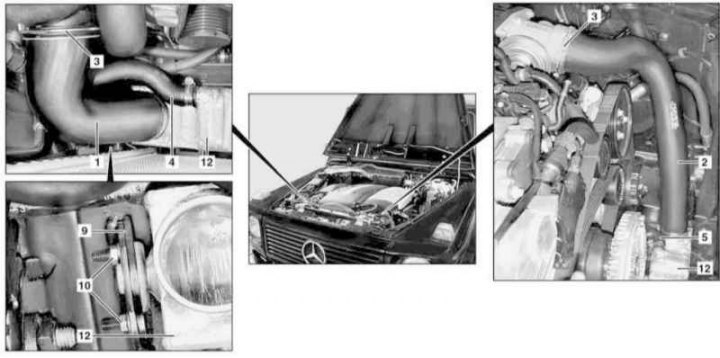
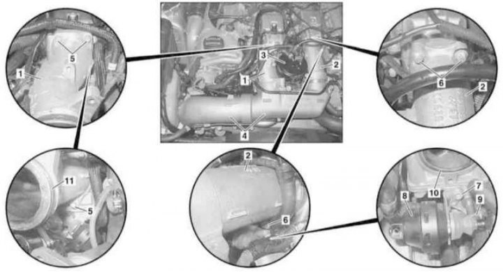
Details of installation of components of an inlet air path (M612)
1. Empty the cooling system (see chapter Ongoing care and maintenance).
2. Remove suction sleeve (1).
3. Disconnect the air hose from the turbocharger (2), - do not forget to disconnect the wiring (3) and hose (4) crankcase ventilation.
4. Remove the cooling fan assembly (see chapter Refrigeration, heating, ventilation and air conditioning systems), - do not forget to install the air conditioning radiator/condenser protection screen (400x680x1 mm metal or plastic plate fitted with a suitable support bracket).
5. Remove the coolant hose (5).
6. Disconnect the coolant hose (6) from the water pump.
7. Release clamp (9) and remove the air sleeve (7), - the presence of a small amount of oil in the sleeve is permissible and is explained by the normal functioning of the crankcase ventilation system.
8. Turn out bolts (10), release the bolt (11) and remove the duct (12) boost path.
9. Installation is carried out in the reverse order. Don't forget to check the condition of the o-rings (8), replace if necessary. Make sure the mounting clamp is seated correctly (9).
Mixing chamber
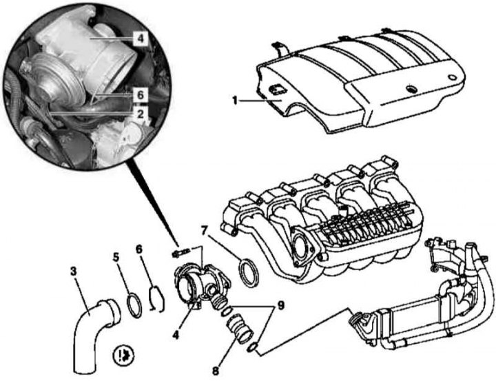
Installation details of the mixing chamber of the air path (M612)
1. Remove the panel (1) air diffuser finishes.
2. Disconnect the vacuum hose (2).
3. Release the circlip (6) and disconnect from the mixing chamber (4) air sleeve (3), - prepare a replacement sealing ring (5).
4. Remove the mixing chamber (4), - do not forget to prepare a replacement sealing element (7).
5. Remove the nozzle (8).
6. Thoroughly clean the seating surface of the mixing chamber.
7. Installation is carried out in the reverse order. Check for a secure fit of the snap ring (6).
Air distributor
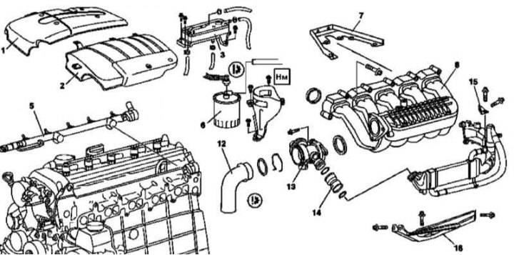
Air distributor installation details (M612) (1 of 3)
Air distributor installation details (M612) (2 of 3)
Air distributor installation details (M612) (3 of 3)
1. Open the hood and lock it in an upright position.
2. Remove panels (1 and 2) cylinder head cover finishes.
3. Appropriate models (code ET2) activate the service mode of the TELE AID emergency call system (see Section Activation / deactivation of the service mode of the TELE AID emergency call system).
4. Disconnect the negative cable from the battery.
5. Remove the crankcase protection.
6. Empty the cooling system (see chapter Ongoing care and maintenance).
7. Appropriate models (code H12) remove auxiliary heater (see chapter Refrigeration, heating, ventilation and air conditioning systems).
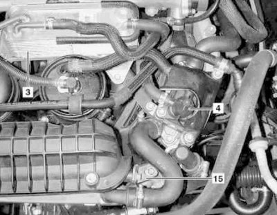
8. Remove the fuel cooler (3).
9. Remove the fuel heater (4).
10. Remove the fuel line (5) (see Section Removal and installation of the fuel distributive highway and nozzles).
11. Remove the carrier mounting brackets from the trunk (5).
12. Remove the main fuel filter (6).
13. Unbolt the top support (7) air distributor (8).
14. Using a hand pump, pump out the hydraulic fluid from the steering pump reservoir (11) (see chapter Ongoing care and maintenance).
15. Disconnect from steering pump (11) hydraulic hose (10), - Seal the open ends of the hose and union immediately.
16. Remove the steering pump reservoir (9) (see chapter Suspension and steering).
17. Disconnect the vacuum lines at the mixing chamber control box.
18. Detach the air sleeve (12) from mixing chamber (13), - if necessary, prepare replacement fastening clamps.
19. Remove the mixing chamber (13) (see above).
20. Dismantle the nozzle (14), - prepare replacement sealing rings.
21. Remove the thermostat cover (see chapter Refrigeration, heating, ventilation and air conditioning systems).
22. Remove the support bracket (15) attachment to the air diffuser (8) path of the exhaust gas recirculation system (EGR).
23. Disconnect the electrical wiring behind the air distributor (8) (heater, CKP sensor and inlet shutoff actuator).
24. Screw off the air distributor (8) from bottom support bracket (16).
25. Installation is carried out in the reverse order - make sure that all seating surfaces are cleaned in the most thorough way, do not forget to replace failed sealing elements.
26. Finally, check the relevant components of the engine cooling system for signs of leak development, deactivate the service mode of the TELE AID system (see Section Activation / deactivation of the service mode of the TELE AID emergency call system) and clear the OBD memory (see chapter Engine Electrical Systems).
Inlet port cut-off motor
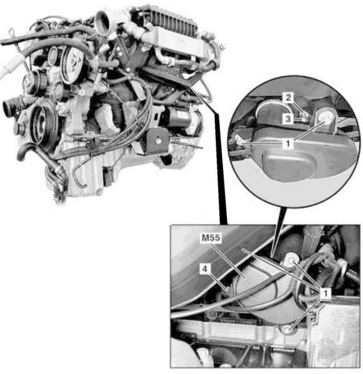
Installation details of the inlet port cut-off motor drive (M612)
1 - Bolt; 2 - Spherical support; 3 - Rack; 4 - Electrical wiring connector; M55 - Electric motor for shutting off the intake port
1. On models of the corresponding configuration (code ET2) activate the service mode of the TELE AID emergency call system (see Section Activation / deactivation of the service mode of the TELE AID emergency call system).
2. Turn on the auxiliary battery and connect it to the standard battery, then disconnect the negative wire from the latter and insulate the pole terminal to prevent it from being accidentally shorted to the W10 ground point.
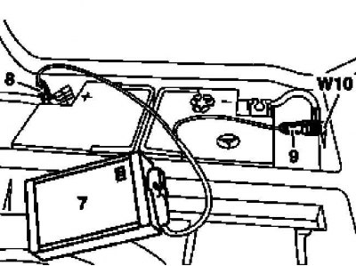
7 - Auxiliary battery
8 - Module positive wire terminal
9 - Terminal of the negative wire of the module
W10 - Battery Ground
3. Jack up the car and put it on stands.
4. Remove the crankcase protection.
5. Empty the cooling system (see chapter Ongoing care and maintenance).
6. Remove the air duct of the boost path (see above).
7. Remove the bolt (1) and remove the rack (3) from the head of the spherical bearing (2), - be careful not to damage the stand.
8. Disconnect the connector (4) electrical wiring and remove the electric motor (M55) inlet port shutoff actuator.
9. Installation is carried out in the reverse order. Do not forget to deactivate the service mode of the TELE AID system (see Section Activation / deactivation of the service mode of the TELE AID emergency call system) and clear the memory of the on-board self-diagnosis module (see chapter Engine Electrical Systems).
Turbocharger
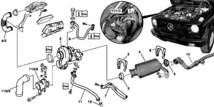
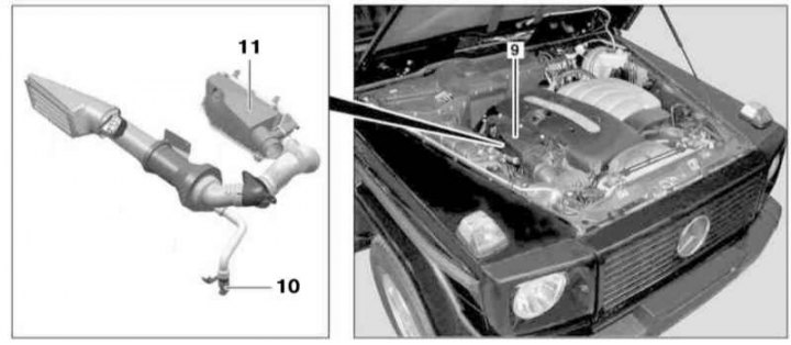
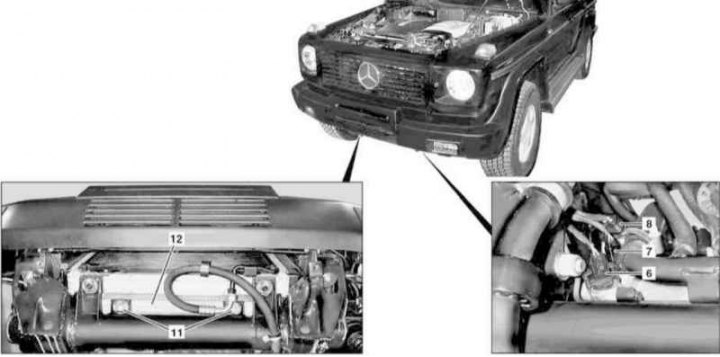
Turbocharger Installation Details (M612)
1. Remove the cylinder head cover trim panels.
2. Remove the air cleaner (see above).
3. Remove the crankcase protection.
4. Disconnect the supply vacuum line (1) from the transducer (Y31/5) boost pressure control.
5. Remove the air duct of the boost path (see above).
6. Remove the clamp (2) turbocharger mounts (3) to primary catalytic converter (4), - prepare replacement sealing cone (5).
7. Loosen the oil supply line (6) from the engine crankcase and turbocharger (3), - prepare replacement sealing elements.
8. Unscrew the support bracket (7) from the underside of the turbocharger (3).
9. Remove clamp (8) fixing the primary catalytic converter (4) to the exhaust pipe (10), - prepare replacement sealing cone (5).
10. Separate the primary catalytic converter (4) from the engine crankcase.
11. Turn out bolts of fastening of a turbocharger (3) to the exhaust manifold.
12. Pushing up, remove the turbocharger (3) from the engine compartment along with the oil drain line (11), - prepare the replacement sealing element.
13. Disconnect from the turbocharger (3) drainage line (10), - prepare to collect spilled oil, if necessary, prepare a replacement sealing element.
14. Installation is carried out in the reverse order. Make sure that the turbocharger is mounted on the bracket (7) without distortion or stress.
15. Finally, check the level of the relevant working fluids and clear the memory of the processor of the on-board self-diagnosis system (see chapter Engine Electrical Systems).
Air cooler
Installation details of the charge air cooler on models with the M612 engine (1 of 2)
Installation details of the charge air cooler on models with the M612 engine (2 of 2)
1. Remove the crankcase protection.
2. Empty the cooling system (see chapter Ongoing care and maintenance).
3. Remove the radiator (see chapter Refrigeration, heating, ventilation and air conditioning systems).
4. Release the fixing straps (3) and remove the left (2) and right (1) air intakes, - if necessary, replace the sealing ring.
Note. The presence of a small amount of oil in the sleeves is acceptable and is due to the normal functioning of the crankcase ventilation system.
5. Disconnect the coolant hoses (4 and 5).
6. Having previously marked the connectors, disconnect the electrical wiring from the coolant temperature sensors (6 and 7).
7. Disconnect the wiring from the boost pressure sensor (8).
8. Give nuts (10) and remove the support bracket (9).
9. Remove the mounting straps (11) and remove the charge air cooler (12), - the cooler must first be separated from the bracket, then pulled up and out.
10. Installation is carried out in the reverse order - make sure that the mounting clamps fit correctly (3).
11. In conclusion, clear the memory of the processor of the on-board self-diagnosis system (see chapter Engine Electrical Systems).
Resonator chamber with water collector
See Section Removal and installation of components of an inlet air path.
Models 463.333 (M628)
Air cleaner and air filter
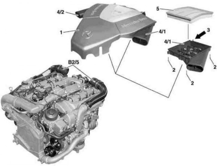
Air cleaner element installation details (M628)
1. Pull up to remove the power unit cover with built-in air cleaner (1).
2. Turn out fixing bolts (2), release the latches (3) and remove trim panels (4/1 and 4/2).
3. Remove the filter element (5) and install a replaceable one instead - make sure the element fits correctly.
4. Further installation is carried out in the reverse order to the dismantling of the components.
Air intake assemblies with air mass sensors (MAF)
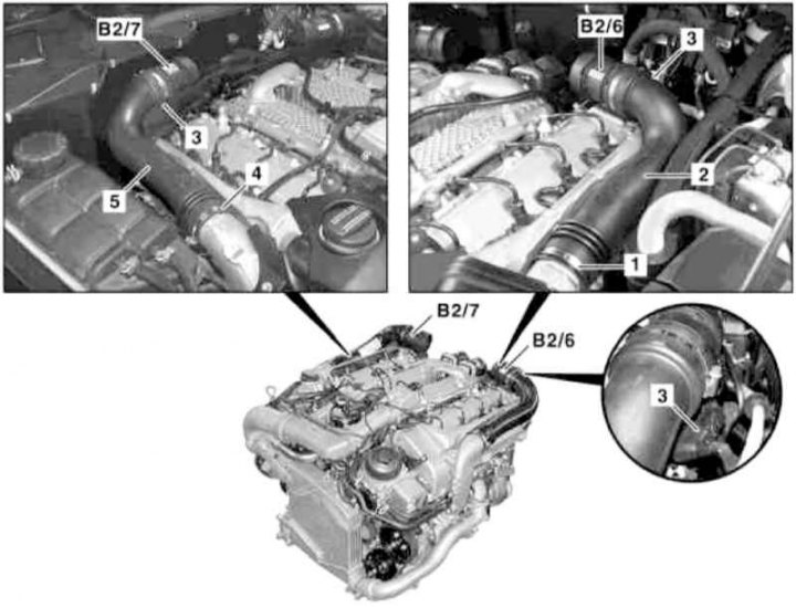
Installation details of air intakes with integrated MAF sensors (M628)
1, 4 - Clamps; 2 - Left air intake; 3 - Connectors; 5 - Right air intake; В2/6 - Left MAF sensor; В2/7 - Right MAF sensor
1. Remove the air cleaner (see above).
2. Disconnect the connectors (3) electrical wiring left (B2/6) and right (B2/7) MAF sensors.
3. Release the fixing straps (1 and 4) and dismantle the air intakes (2 and 5) with built-in MAF sensors (B2/6 and B2/7 respectively).
4. Installation is carried out in the reverse order.
Intake air temperature sensor (IAT)
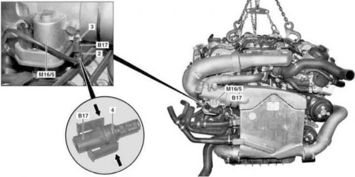
IAT sensor installation details (diesel models with M628 engine)
2 - connector; 3 - Mounting brackets; 4 - O-ring; B17 - IAT sensor; M16 / 5 - Throttle actuator actuator
1. Remove the air cleaner (see above).
2. Remove the cooling fan shroud (see chapter Refrigeration, heating, ventilation and air conditioning systems).
3. Remove the mounting band from the mounting brackets (3), - the bandage must be replaced without fail.
4. Disconnect the connector (2) IAT sensor wiring (B17).
5. Squeeze the mounting brackets (arrows) and remove the IAT sensor (B17).
Attention! To prevent damage to mounting brackets (3) do not remove or install the IAT sensor with the wiring connected - in case of damage to the brackets, the sensor must be replaced without fail!
6. Installation is in reverse order - do not forget to replace the sealing ring (4).
7. Finally, clear the memory of the on-board self-diagnosis module (see chapter Engine Electrical Systems).
Air ducts of the pressurization path
Left inlet sleeve
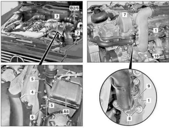
Details of installation of the left inlet sleeve of a way of pressurization of air (M628)
1. Jack up the car and put it on stands.
2. Remove the air cleaner (see above).
3. Remove the left air intake assembly (2) complete with MAF sensor (B2/6) (see above) and pull it back in the wheel arch.
4. Remove the cover (3) oil filter housing.
5. Remove the additional heater block (A6) (see chapter Refrigeration, heating, ventilation and air conditioning systems).
6. Turn out bolts (5), loosen one nut on the longitudinal beam of the frame, disconnect the support bracket from the frame (6) and remove the heat shield (4).
7. Remove the bolt (7) and remove the fan assembly shroud (see chapter Refrigeration, heating, ventilation and air conditioning systems).
8. Install the air conditioning radiator/condenser shield (400x680x1 mm metal or plastic plate fitted with a suitable support bracket).
9. Remove the left lower air duct (see below).
10. Turn out bolts (8) from connecting flange (9) cooling path.
11. Release clamp (10) and remove the left inlet sleeve of the charge air path (1).
12. Installation is carried out in the reverse order.
Right inlet sleeve
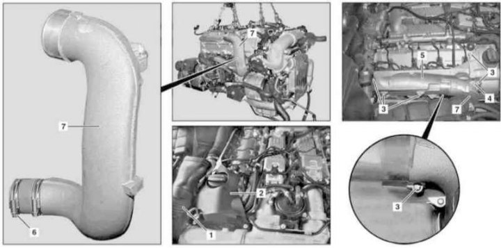
Details of installation of the right inlet sleeve of a way of pressurization of air (M628)
1 - Air intake; 2 - Finishing panel; 3, 4 - Bolts; 5 - Cover; 6 - Clamp; 7 - Right inlet sleeve
1. Jack up the car and put it on stands.
2. Remove the air cleaner (see above).
3. Remove the left air intake assembly (2) complete with MAF sensor (B2/6) (see above) and pull it back in the wheel arch.
4. Remove the panel (2) oil filler trim.
5. Turn out bolts (3 and 4) and remove the cylinder head cover (5).
6. Remove fan assembly shroud (see chapter Refrigeration, heating, ventilation and air conditioning systems) and install the air conditioning radiator/condenser shield (400x680x1 mm metal or plastic plate fitted with a suitable support bracket).
7. Remove the right lower air duct (see below).
8. Release clamp (6) and remove the left inlet sleeve of the charge air path (7).
9. Installation is carried out in the reverse order.
Left lower air duct
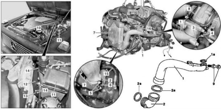
Installation details of the left lower air duct of the boost path (M628)
1. Jack up the car and place it on jack stands
2. Remove the air cleaner (see above).
3. Release the air intake (10) in the wheel arch.
4. Remove fan assembly shroud (see chapter Refrigeration, heating, ventilation and air conditioning systems) and install the air conditioning radiator/condenser shield (400x680x1 mm metal or plastic plate fitted with a suitable support bracket).
5. Remove the auxiliary heater block (see chapter Refrigeration, heating, ventilation and air conditioning systems).
6. Turn out bolts (14), loosen one nut on the longitudinal beam of the frame, disconnect the support bracket from the frame (13) and remove the heat shield (12).
7. Turn out bolts (3 and 5) and remove the connecting plates (4 and 6).
8. Pinch the low-pressure steering pump reservoir hose (16) and disconnect the high-pressure hose from the latter (15), - get ready to collect the spilled hydraulic fluid, plug the open ends of the line and the connecting fitting immediately.
9. Turn out fixing bolts (9), then pull back the duct (1) complete with connecting pipe (2) from the turbocharger (8) and charge air cooler (7) and remove it by pushing forward.
10. Installation is carried out in the reverse order - if necessary, replace the sealing rings (1a and 2a).
11. In conclusion, do not forget to remove air from the power steering tract (see chapter Suspension and steering).
Right lower air duct
Installation details of the right lower air duct of the boost path (M628)
1. Jack up the car and place it on jack stands
2. Remove the air cleaner (see above).
3. Remove fan assembly shroud (see chapter Refrigeration, heating, ventilation and air conditioning systems) and install the air conditioning radiator/condenser shield (400x680x1 mm metal or plastic plate fitted with a suitable support bracket).
4. Turn out bolts (3) and remove the connecting plate (4).
5. Turn out bolts (11 and 6).
6. Turn out bolts (7) and remove the connecting plate (8).
7. Pull back the duct (1) complete with connecting pipe (2) from the turbocharger (9) and charge air cooler (10) and remove it by pushing it back.
8. Installation is carried out in the reverse order - if necessary, replace the sealing rings (1a and 2a).
Intermediate ducts
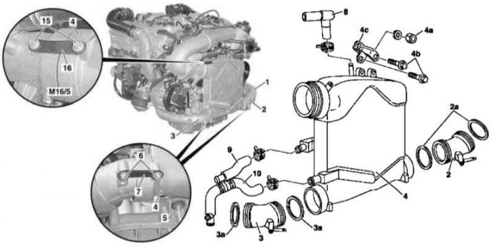
Details of the installation of intermediate air ducts of the pressurization path (M628)
1 - Right intermediate air duct; 2 - Left intermediate air duct; 3 - Fuel filter; 4 - Throttle actuator actuator with upper air ducts; 5, 6, 7 - Screws; 8 - Vacuum drive block for shutting off the inlet port; 9 - Thrust; 10, 11 - O-rings
1. Remove the air cleaner (see above).
2. Remove the throttle actuator assembly with the upper air ducts (4) (see below).
3. Remove the fuel filter.
4. Turn out bolts (5) and remove the right intermediate air duct (1).
5. Disconnect the vacuum block (8) drive for shutting off the intake port from thrust (9), then remove the bolt (7) and take the block (8) to the side.
6. Turn out bolts (6) and remove the left intermediate air duct (2).
7. Installation is carried out in the reverse order - if necessary, replace the sealing rings (10 and 11).
Air distributor
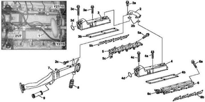
Details of installation of the air distributor on models with the M628 engine (1 of 2)
1 - Vacuum line of the brake booster; 2 - Connecting pipe; 2a, 2c, 3a, 3c, 4c, 5a, 6a - Bolts; 2b, 3d, 4d - O-ring; 3 - Upper half of the right section of the air distributor; 3b, 4b, 5b, 6b - Gaskets; 4 - Upper half of the left section of the air distributor; 5, 6 - Air distribution lines with shutdown of intake ports; 5s, 6s - Vacuum control units; 7 - EGR cooler; 8 - Rear connecting node of the EGR cooler; 9 - Front connecting node of the EGR cooler; 21/7 - Valve block; Y27 / 9 - Left activator EGR; Y27/10 - Right EGR activator
Details of installation of the air distributor on models with the M628 engine (2 of 2)
1. Remove the air cleaner (see above).
2. Remove air intake assemblies with MAF sensors (see above).
3. Remove fan assembly shroud (see chapter Refrigeration, heating, ventilation and air conditioning systems).
4. Remove the throttle actuator assembly with the upper air ducts.
5. Remove intermediate ducts (see above), - if necessary, prepare replacement sealing rings (3d and 4d).
6. Remove the vacuum line (1) brake booster.
7. Remove the fuel distribution line (see Section Removal and installation of the fuel distributive highway and nozzles), - only on the left.
8. Remove the EGR activators (Y27/9 and Y27/10)
9. Turn out bolts (2a) and remove the connecting pipe (2), - if necessary, prepare replacement sealing rings (2b).
10. Turn out bolts (4a and 4c) and remove the upper half of the left section of the air distributor (4), - prepare the replacement gasket (4b).
11. Remove the vacuum block (21/7).
12. Turn out bolts (3a and 3c) and remove the upper half of the right section of the air distributor (3), - prepare the replacement gasket (3b).
13. Disconnect the vacuum hoses from the vacuum control units (5s and 6s).
14. Remove the EGR cooler (7) (see Section Removing and installing the EGR cooler).
15. Turn out bolts (5a and 6a) and remove the air distribution lines (5 and 6) with actuators for shutting off inlet ports.
16. Installation is carried out in the reverse order.
Throttle Actuator Assembly with Top Air Ducts
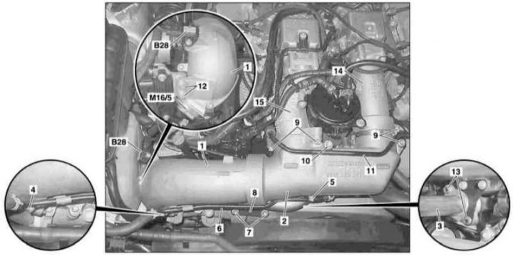
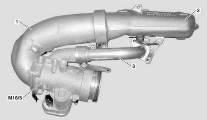
Installation details of the throttle actuator actuator assembly with upper air ducts on models with the M628 engine (1 of 2)
1, 2 - Air ducts; 3 - EGR pipe; 4, 5, 7, 9, 10, 12, 13 - Bolts; 6, 11 - Line of the cooling path; 8 - Connecting plate; 14, 15 - Intermediate air ducts; B28 - Pressure sensor; M16 / 5 - Throttle actuator actuator
Installation details of the throttle actuator actuator assembly with upper air ducts on models with the M628 engine (2 of 2)
1. Remove the air cleaner (see above).
2. Remove fan assembly shroud (see chapter Refrigeration, heating, ventilation and air conditioning systems).
3. Disconnect the electrical wiring from the pressure sensor (B28).
4. Turn out bolts (4, 5) and move aside the line of the cooling path (6).
5. Turn out bolts (7) and remove the connecting plate (8).
6. Turn out bolts (9 and 10) and move aside the line of the cooling path (11).
7. Turn out bolts (12 and 13) and disconnect the EGR pipe (3), - prepare a replacement sealing ring.
8. Separate the duct (2) from intermediate sleeves (14 and 15), prepare replacement O-rings.
9. Disconnect wiring from throttle actuator (М16/5).
10. Remove the IAT sensor (see above).
11. Pull to separate the activator (М16/5) from the charge air cooler and remove it complete with air ducts (1 and 2) and EGR pipe (3), - if necessary, prepare replacement sealing rings.
12. Installation is carried out in the reverse order - damaged sealing elements must be replaced.
Turbochargers
Right turbocharger
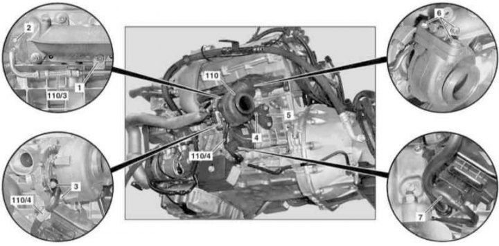
Installation details of the right turbocharger (M628)
1. Jack up the car and put it on stands.
2. Remove the crankcase protection.
3. Disconnect the negative cable from the battery.
4. Remove the catalytic converter / front section of the exhaust system (see Section Removal and installation of system of release of the fulfilled gases).
5. Remove the air cleaner and air intake assembly with MAF sensor (see above).
6. Remove fan assembly shroud (see chapter Refrigeration, heating, ventilation and air conditioning systems).
7. Remove the right bottom air duct (9) and inlet hose of the pressurization system (10) (see above).
8. Remove the starter (see chapter Engine Electrical Systems).
9. Remove the heat shield in the arch of the right front wheel.
10. Give the nut (1) on the exhaust manifold and bolt (2) oil supply lines (110/3) on the cylinder head, - prepare a replacement sealing ring.
Note. Self-locking nut (1) must be replaced without fail, if necessary, also replace the bolt.
11. Turn out bolts (3) turbocharger attachments (110) oil return lines (110/4) and pull the latter away from the engine - get ready to collect spilled oil and pick up replacement seals (from the turbocharger side) and sealant (from the engine side).
12. Turn out a bolt (4) on a support (5) turbocharger (110).
13. Turn out bolts (6), disconnect the connector (7) and release the wiring harness from the clamps (8).
14. Filing back, remove the turbocharger (110), then unbolt the oil supply line from it (110/3), - prepare a replacement gasket.
15. Installation is carried out in the reverse order.
16. Finally, check the levels of the respective fluids and correct if necessary.
Left turbocharger
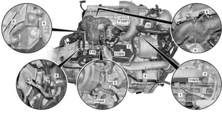
Details of installation of the left turbocharger (M628)
1. Jack up the car and put it on stands.
2. Remove the crankcase protection.
3. Disconnect the negative cable from the battery.
4. Remove the catalytic converter / front section of the exhaust system (see Section Removal and installation of system of release of the fulfilled gases).
5. Remove the air cleaner and air intake assembly with MAF sensor (see above).
6. Remove fan assembly shroud (see chapter Refrigeration, heating, ventilation and air conditioning systems).
7. Remove the auxiliary heater block (see chapter Refrigeration, heating, ventilation and air conditioning systems).
8. Remove the left lower air duct (8) and inlet hose of the pressurization system (9) (see above).
9. Remove the heat shield in the arch of the left front wheel.
10. Give the nut (1) on the exhaust manifold and bolt (2) oil supply lines (110/3) on the cylinder head, - prepare a replacement sealing ring.
Note. Self-locking nut (1) must be replaced without fail, if necessary, also replace the bolt.
11. Turn out bolts (3) turbocharger attachments (110) oil return lines (110/4) and pull the latter away from the engine - get ready to collect spilled oil and pick up replacement seals (from the turbocharger side) and sealant (from the engine side).
12. Turn out a bolt (4) on a support (5) turbocharger (110).
13. Turn out bolts (6), disconnect the connector (7) and release the wiring harness from the clamps (8).
14. Filing back, remove the turbocharger (110), then unbolt the oil supply line from it (110/3), - prepare a replacement gasket.
15. Installation is carried out in the reverse order.
16. Finally, check the levels of the respective fluids and correct if necessary.
Air cooler
Installation details of the charge air cooler on models with the M628 engine (1 of 2)
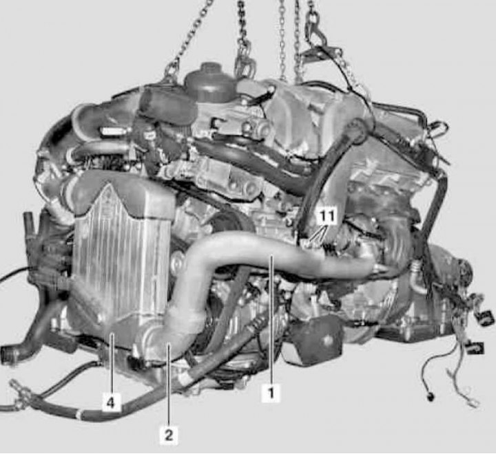
Installation details of the charge air cooler on models with the M628 engine (2 of 2)
1. Jack up the car and put it on stands.
2. Remove the air cleaner (see above).
3. Remove the crankcase protection.
4. Install the air conditioning radiator/condenser shield (400x680x1 mm metal or plastic plate fitted with a suitable support bracket).
5. Turn out bolts (5).
6. Give the nut (4a), remove the bolt (4b) and remove the support bracket (4s).
7. Empty the cooling system (see chapter Refrigeration, heating, ventilation and air conditioning systems).
8. Disconnect the cooling path lines (8, 9 and 10).
9. Turn out bolts (15 and 6) and remove the connecting plates (16 and 7).
10. Turn out bolts (11) and separate the duct (1) complete with intermediate sleeve (2) from charge air cooler assembly (4).
11. Separate from the air duct (1) and remove the intermediate sleeve (2).
12. Separate coolant (4) from throttle actuator (М16/5) with intermediate duct (3) and remove it from the engine compartment.
13. Installation is carried out in the reverse order - do not forget to replace the failed sealing elements (2a and 3a).
14. Finally, fill the cooling system, correct the coolant level and check the system path for signs of leak development.
Resonator chamber with water collector
See Section Removal and installation of components of an inlet air path.