
Note. If necessary, each of the sections of the exhaust system can be removed individually.
Attention! All self-locking elements of threaded fasteners must be replaced without fail!
Petrol models
Models 463.249/250 standard
Except models 463.250 (code K89) and 463.246 (AMG)
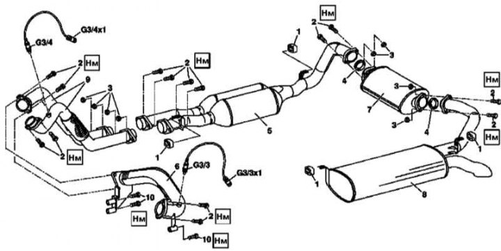
Details of installation of components of system of release of the fulfilled gases on models 463.249/250 of release on 30.11.00
1, 8 - Rubber hangers; 2 - Bolts of flange connections; 3 - Nuts of flange connections; 4 - O-ring; 5 - Catalytic converter; 6 - Cross section; 7 - Main muffler; 8 - Rear muffler; 9 - Front sections; 10 - Bolts for fastening the transverse section; G3 / 3 - Left pre-catalytic lambda probe; G3 / 3x1 - Connector for the wiring of the left pre-catalytic lambda probe; G3 / 4 - Right pre-catalytic lambda probe; G3/4x1 - Right pre-catalytic lambda probe wiring connector

Scheme of fastening the lower section of the exhaust system (only models 463.250)
11 - Support brackets
1. Remove the right pre-catalytic lambda probe (G3/4) from the front section of the exhaust system and disconnect the electrical wiring from it (G3/4x1).
2. Turn out the left pre-catalytic lambda probe (G3/3) from the cross section of the exhaust system (6) and disconnect the wiring (G3/3x1).
3. Loosen bolted connections (2/3) and separate the flange of the left front section (9) exhaust system from the right exhaust manifold, - if necessary, replace the nuts (3).
4. On models 463.250, remove the brackets (11) mounting the lower section of the exhaust system.
5. Loosen bolted connections (2/3) and separate the cross section flange (6) exhaust systems from the right front section (9), - if necessary, replace the nuts (3).
6. Proceeding in a similar manner, separate the cross section from the left exhaust manifold - if necessary, replace the nuts (3).
7. Turn out bolts (10) and separate the cross section (6) from the transmission case.
8. Separate the flange connections of the fastening of the catalytic converters (5) to the front sections (9) exhaust system and to the main muffler (7).
9. Remove the catalytic converter section (5) with rubber hangers (1), - if the catalytic converters are to be removed, release both brackets.
10. Separate the main muffler (7) from the rear muffler (8).
11. Loosen the bracket and remove the rear muffler (8) with rubber hangers (1).
12. Installation is carried out in the reverse order - damaged sealing rings and rubber hangers must be replaced without fail. The same goes for nuts (3) flange connections. Make sure that the sections of the exhaust system are installed without stress.
Note. Damaged components of the exhaust system must be replaced without fail.
Models 463.250 with code K89 (G320)
Attention! When disposing of three-function catalytic converters (TWC) the requirements of federal environmental protection legislation must be observed!
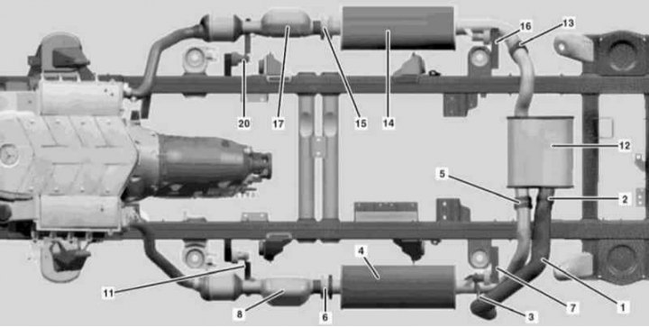
Details of installation of components of system of release of the fulfilled gases on models 463.250 with code K89 (1 of 3)
1 - Outlet pipe; 2, 13 - Mounting clamps; 3, 7, 11, 16, 20 - Brackets; 4 - Left front muffler; 5, 6, 15 - Flange connections; 8 - Left catalytic converter; 12 - Main muffler; 14 - Right front muffler; 17 - Right catalytic converter
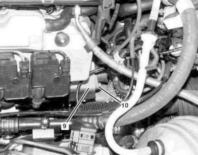
Details of installation of components of system of release of the fulfilled gases on models 463.250 with code K89 (2 of 3)
9 - The upper section of the heat shield
10 - Flange connection
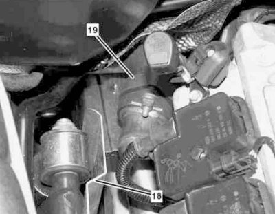
Details of installation of components of system of release of the fulfilled gases on models 463.250 with code K89 (3 of 3)
18 - The upper section of the heat shield
19 - Flange connection
1. Release the clamp (2) and separate the exhaust pipe (1) from the main muffler (12).
2. Unbolt the exhaust pipe (1) from support bracket (3) and remove it from under the car.
3. Loosen the flange connections (5 and 6) mounting left front muffler (4).
4. Remove muffler (4) from support bracket (7).
5. Disconnect the wiring from the upper and lower lambda probes on the left catalytic converter (8).
6. Remove the top section of the heat shield (9).
7. Loosen the flange connection (10) left front section of the exhaust system.
8. Separate the bracket (11) from frame and left catalytic converter (8).
9. Loosen the flange connection (13) main muffler mounting (12) to right front muffler (14).
10. Remove the main muffler (12).
11. Loosen the flange connection (15) mounting right front muffler (14) to catalytic converter (17).
12. Separate the bracket from the frame (16) and remove the right front muffler (14).
13. Disconnect the wiring from the upper and lower lambda probes on the right catalytic converter (17).
14. Remove the top section of the heat shield (18).
15. Loosen the flange connection (19) fixing the right catalytic converter (17) to the right front section.
16. Disconnect the bracket from the frame (20) and remove the right catalytic converter assembly (17).
17. Installation is carried out in the reverse order - make sure that the sections of the exhaust system are installed without tension.
Note. Damaged components of the exhaust system must be replaced without fail.
Models 463.246 (G55 AMG)
Attention! When disposing of three-function catalytic converters (TWC) the requirements of federal environmental protection legislation must be observed!
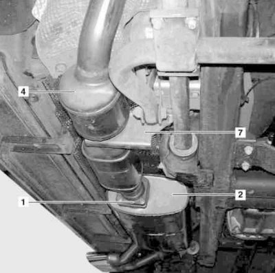
Details of installation of components of system of release of the fulfilled gases on models 463.246 (1 of 3)
1 - Flange connection
2 - Rear muffler
3 — TWC
4 - Bracket
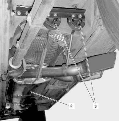
Details of installation of components of system of release of the fulfilled gases on models 463.246 (2 of 3)
2 - Rear muffler
3 - Hangers
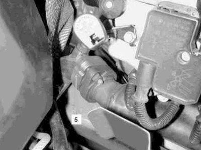
Details of installation of components of system of release of the fulfilled gases on models 463.246 (3 of 3)
5 - Flange connection
1. Loosen the flange connection (5) left lower section of the exhaust system.
2. Loosen the flange connection (1) on rear muffler assembly (2).
3. Remove the bracket from the frame (7) and dismantle the TWC unit (4).
4. Remove the rear muffler (2) from hangers (3) and remove it from under the car.
5. Disconnect the electrical wiring from the lambda probes at the top and bottom of the catalytic converter assembly (4), - fastening strapping should be cut.
6. Remove the top section of the left heat shield.
7. Installation is carried out in the reverse order - do not forget to install new harnesses for fastening the electrical wiring of the lambda probes.
Note. Damaged components of the exhaust system must be replaced without fail.
Diesel models
Attention! When disposing of three-function catalytic converters (TWC) the requirements of federal environmental protection legislation must be observed!
Models 463.323 (M612)
The main components of the exhaust system
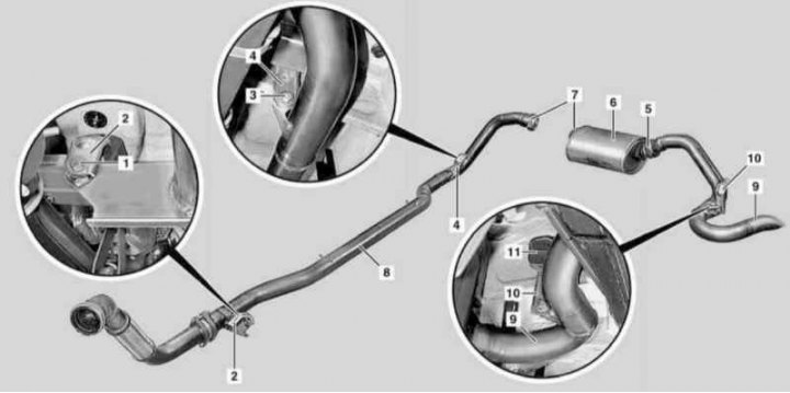
Details of installation of components of system of release of the fulfilled gases on models 463.323 (M612)
1, 3 - Bolts; 2 - Front bracket; 4 - Rear bracket; 5, 7 - Flange connections; 8 - Middle section; 9 - Outlet pipe; 10 - Bracket; 11 - Rubber hanger
1. Loosen the bolts (1 and 3) front mounts (2) and rear (4) brackets.
2. Release the left (5) and right (7) flange connections on the rear muffler (6), which should be pre-supported. Prepare a replacement sealing cone.
3. Unbolt the middle section of the exhaust system (8) from the front (2) and rear (4) brackets and remove it from under the car, it would be wise to enlist the help of an assistant.
4. Loosen the flange connection (5) rear muffler mounts (6) exhaust pipe (9), - prepare a replacement sealing cone.
5. Remove the rear muffler (6) and exhaust pipe (9).
6. Installation is carried out in the reverse order.
Note. Damaged components of the exhaust system must be replaced without fail.
Replacing the primary catalytic converter
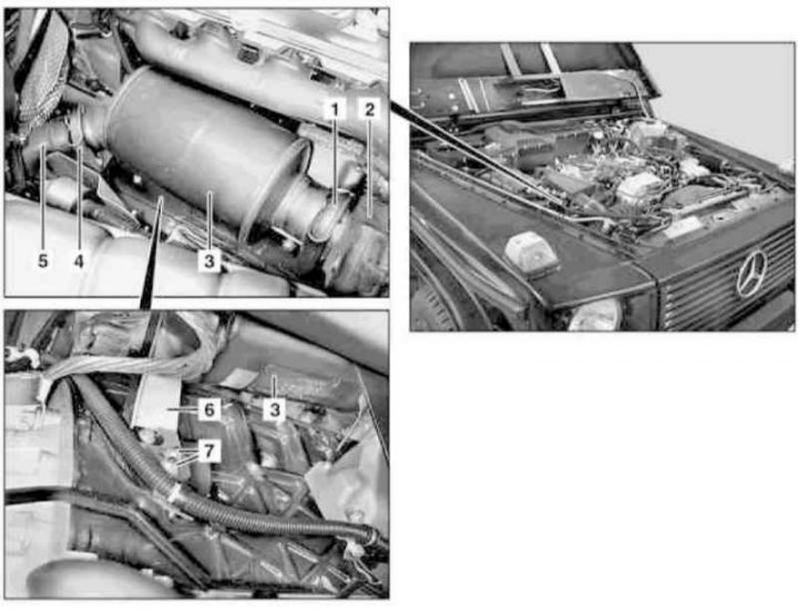
Installation details of the primary catalytic converter on models 463.323 (M612)
1, 4 - Clamps; 2 - Turbocharger; 3 - Primary catalytic converter; 5 - Pipe of the exhaust gas system; 6 - Support bracket; 7 - Nuts
1. Remove the cylinder head cover trim panels.
2. Remove the air cleaner (see Section Servicing Air Inlet Components).
3. Remove the clamp (1) turbocharger mounts (2) to primary catalytic converter (3), - prepare a replacement sealing cone.
4. Remove the clamp (4) fixing the primary catalytic converter (3) to the exhaust pipe (5), - prepare a replacement sealing cone.
5. Loosen nuts (7) and remove the bracket (6) catalytic converter mountings (3) to the engine crankcase.
6. Remove the catalytic converter (3).
7. Installation is carried out in the reverse order.
Models 463.333 (M628)
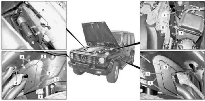
Details of installation of system of release of the fulfilled gases on models 463.333 (M628) (1 of 2)
1, 2 - Covers; 3, 4, 7 - Bolts; 5 - Left thermal screen; 6 - Right thermal shield
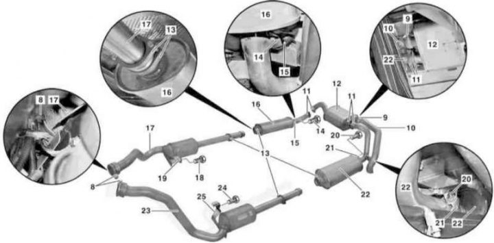
Details of installation of system of release of the fulfilled gases on models 463.333 (M628) (2 of 2)
8, 9, 11, 13 - Mounting clamps; 10 - Outlet pipe; 12 - Main muffler; 14, 18, 20, 24 - Bolts; 15, 19, 21, 25 - Brackets; 16 - Right front muffler; 17 - Right oxidation catalytic converter; 22 - Left front muffler; 23 - Left oxidation catalytic converter
1. Jack up the car and put it on stands.
2. Remove wheel arch lockers (see chapter Body).
3. Turn out fixing bolts (3 and 4) and remove covers (1 and 2).
4. Turn out bolts (7) and remove the left (5) and right (6) thermal screens.
5. Loosen the fastening clamps (8) on turbochargers.
6. Support the main muffler (12) and release the clamps (11).
7. Remove the main muffler (12).
8. Release clamps (13).
9. Support the front muffler assembly and catalytic converter and remove the bolts (14) on bracket (15).
10. Pull back the front muffler (16) from the right catalytic converter (17) and remove it from the vehicle.
11. Remove the bolt (18) on bracket (19) and remove the right catalytic converter (17).
12. Turn out a bolt (20) on bracket (21) and remove the left front muffler (22), by pulling it away from the left catalytic converter (23).
13. Turn out a bolt (24) on bracket (25) and remove the left catalytic converter (23).
14. Remove the exhaust pipe (10).
15. Installation is carried out in the reverse order.
Note. Damaged components of the exhaust system must be replaced without fail.