
Models 463.333 (M628)
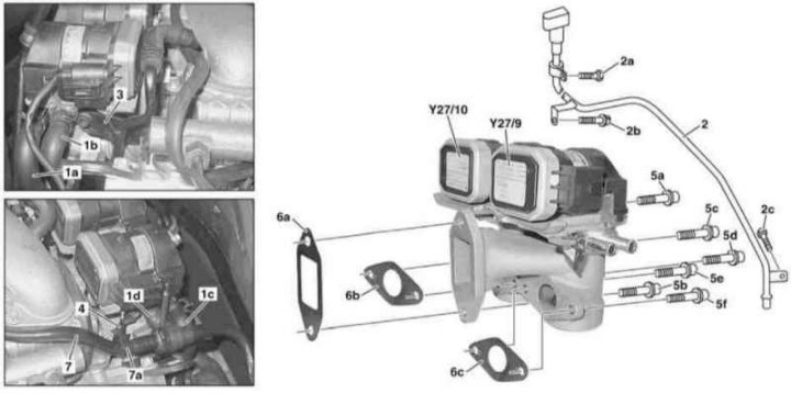
Installation details of EGR positioners on models 463.333 (M628)
1a-1d - Hoses of the cooling path; 2 - ATF filler neck; 2a-2c, 5a-5f - Bolts; 3, 4 - Brackets; 6a-6c - Sealing gaskets; 7 - Pneumatic line; 7a - Clamps; Y27/9 - Left EGR positioner; Y27/10 - Right EGR positioner
1. Empty the cooling system (see chapter Ongoing care and maintenance).
2. Remove the air cleaner (see Section Servicing Air Inlet Components).
3. Remove the left and right air intakes with MAF sensors (see Section Servicing Air Inlet Components).
4. Disconnect wiring from EGR positioners (Y27/9 and Y27/10).
5. Remove the center section of the splash shield.
6. Disconnect the cooling path hoses from the EGR positioners (1a-1d).
7. Turn out bolts (2a, 2b and 2c) and move aside the ATF filler neck (2), - do not remove the dipstick.
8. Remove brackets (3 and 4), bolted to the EGR positioner and air distributor.
9. Release clamp (7a) pneumatic line fittings (7).
10. Turn out bolts (5a-5f) and remove the positioner (Y27/9 and Y27/10).
11. Installation is carried out in the reverse order. Don't forget to replace the sealing elements.