
Preparing to remove the 111 series engine (1 of 4)
Preparing to remove the 111 series engine (2 of 4)
Preparing to remove the 111 series engine (3 of 4)
Preparing to remove the 111 series engine (4 out of 4)
1. Illustrative material for preparing to remove the engine is presented on Ref. illustrations, which include all references in the text.
2. Disconnect the negative cable from the battery.
3. Empty the cooling system (see chapter Coolant Replacement - General Notes).
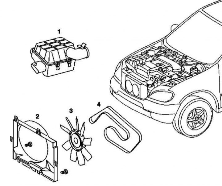
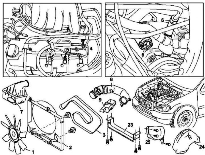
4. Remove the cooling fan assembly (3 - impeller with viscous coupling) (see chapter Cooling, heating and air conditioning systems).
5. Remove the cooling fan shroud (2) (see chapter Cooling, heating and air conditioning systems).
6. Install the A/C radiator/condenser shield.
7. Remove the air cleaner assembly (1).
8. Remove the accessory drive belt (4) (see chapter Engine).
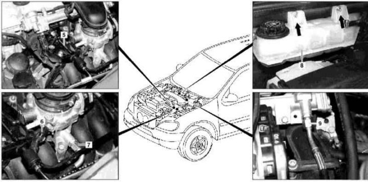
9. Disconnect the throttle linkage (5).
10. Disconnect brake booster vacuum lines (7) and regeneration tract (6).
11. Disconnect the fuel line (9).
12. Remove expansion tank (8).
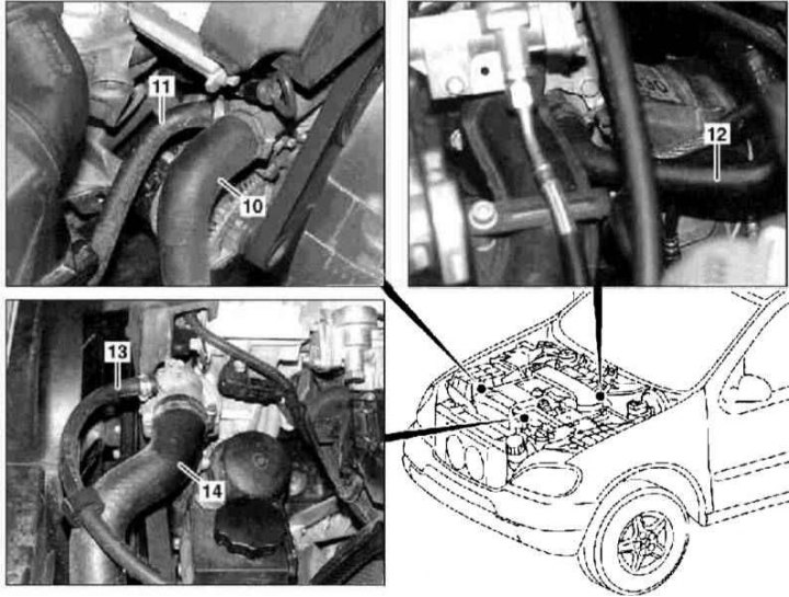
13. Disconnect the hoses of the cooling path (10, 11, 12, 13 and 14)
14. Disconnect the connector (s) engine wiring.
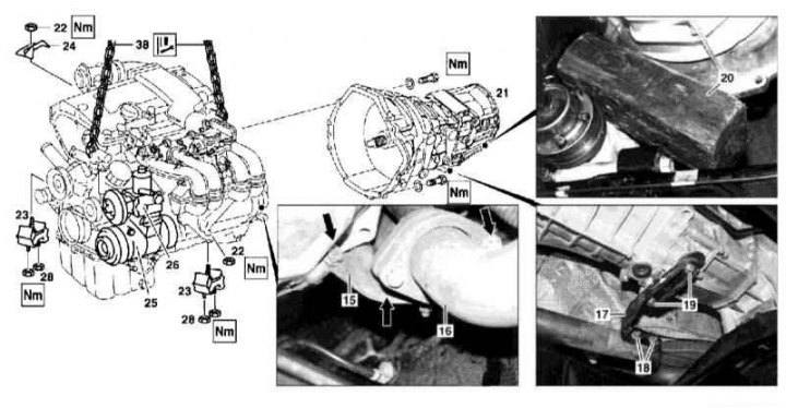
15. Relieve the steering pump (26).
16. Turn out the top bolts of fastening of a dome of transmission to the engine.
17. Remove the starter (see chapter Engine Electrical Systems).
18. Remove the exhaust pipe from the exhaust manifold (16).
19. Unbolt the bracket from the exhaust pipe (15).
20. Turn out bolts of fastening of a basic arm of system of release (17) to the transmission housing.
21. Screw off the A/C compressor (25) and, without disconnecting the lines of the refrigeration path, take the assembly aside and secure it by tying it with wire.
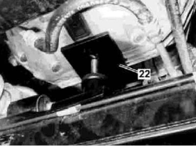
22. Loosen the right and left front suspension mounts of the power unit (23).23 Connect chains (38) lift to the lifting eyes of the power unit.
23. Hang the engine on the winch and support the transmission assembly from below (21).
24. Remove the right suspension bracket of the power unit (23).
25. Turn out the remained bolts of fastening of a dome of transmission to the engine.
26. Carefully separating the engine from the transmission, lift it up and remove it from the engine compartment.
27. Installation is carried out in the reverse order.
M112/113
Preparing to remove the 112 and 113 series engine (on the example of engine 112.942 - 1 out of 5)
Preparing to remove the 112 and 113 series engine (on the example of engine 112.942 - 2 out of 5)
Preparing to remove the 112 and 113 series engine (on the example of engine 112.942 - 3 out of 5)
Preparing to remove the 112 and 113 series engine (on the example of engine 112.942 - 4 out of 5)
Preparing to remove the 112 and 113 series engine (on the example of engine 112.942 - 5 out of 5)
1. Illustrative material for preparing to remove the engine is presented in the illustrations, which include all references in the text.
2. Remove the power unit cover.
3. Make sure that the engine rigging lugs are properly installed - the rear lugs are reinforced.
4. Disconnect the negative cable from the battery.
5. Remove the air baffle (23), - only models equipped with engine 113.942.
6. Disconnecting the hose (16), drain the coolant from the radiator.
7. Drain the engine oil (see chapter Changing the engine oil and oil filter).
8. Remove the viscous cooling fan assembly (1), - except for models equipped with engines 113.981 and 113.965.
Note. The thread is right hand cut.
9. Remove fan shroud (2),
10. On the models equipped with engines 113.981 and 113.965, remove the electric fan of the cooling system.
11. Install the A/C radiator/condenser shield.
12. Remove expansion tank (1).
13. Remove the air cleaner assembly (7).
14. Remove the resonator chamber (9) with connecting sleeve (8) (see chapter Removal and installation of components of an inlet air path).
15. Disconnect the connecting hose from the water pump (15).
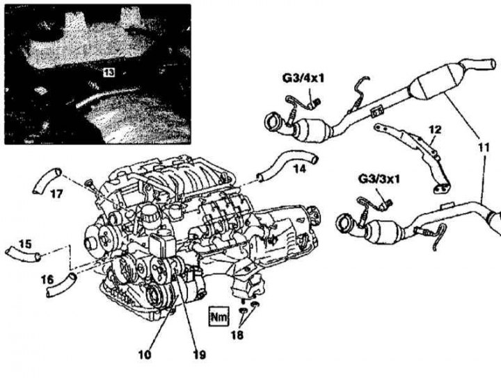
16. Remove the hose (17), from the radiator to the thermostat housing.
17. On models equipped with 113 series engines, remove the radiator (see chapter Cooling, heating and air conditioning systems).
18. Disconnect the vacuum line (5), connecting the brake booster servo to the rear of the intake manifold.
19. Pump out oil from the steering pump (19).
20. Disconnect from steering pump assembly (19) pressure and return lines, - plug the open ends of the lines immediately to prevent dirt from entering the hydraulic system.
21. Disconnect the vacuum line from the inlet pipeline (6) regeneration tract.
22. Disconnect the fuel line (4).
23. Remove the line of the cooling path (14).
24. Remove the accessory drive belt (3) (see chapter Engine).
25. Disconnect the electrical wiring from the A/C compressor (10).
26. Turn out fixture and disconnect the K/V compressor (10) from the timing cover.
27. Remove the left front wheel arch protection locker (24) (models with 113 series engines).
28. Remove deflector (25) (models with 113 series engines).
29. Disconnect the exhaust pipes from the exhaust manifolds (11).
30. Disconnect the support bracket for the exhaust system (12).
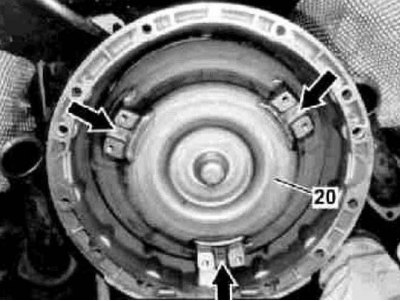
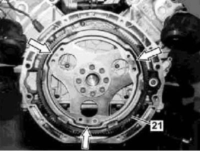
31. Unbolt the rotation converter (20) from the gear rim of the engine start (21).
32. Disconnect the electrical wiring connectors of the left and right pre-catalytic lambda probes (G3/3x1 and G3/4x1) on the transmission housing.
33. Turn out bolts of fastening of a starter, - do not disconnect electroconducting.
34. Loosen the bolts securing the transmission dome to the engine, remove all bolts except for the top two (112 series engines) /lower (113 series engines).
35. Give the nuts of the suspension mounts of the power unit (18).
36. On models with АТ turn out an oil filling tube on the right head of cylinders.
37. Connect winch chains to engine rigging eyes.
38. Hang the engine and support the transmission (22).
39. Turn out the remained two bolts of fastening of transmission to the engine, and carefully take out the last from a motor compartment of the car.
40. Installation is carried out in the reverse order.