
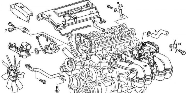
Preparing to remove the cylinder head of the 111 series engine
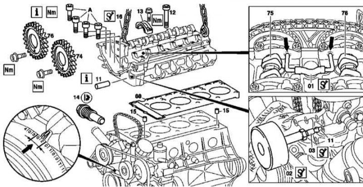
Removing the cylinder head of the 111 series engine
1. Illustrative material for removing and installing the cylinder head of the 111 series engine is shown in the illustrations, which include all references in the text.
2. Empty the cooling system (see chapter Ongoing care and maintenance).
3. Remove the expansion tank of the cooling system (see chapter Cooling, heating and air conditioning systems).
4. Unscrew the front pipe from the exhaust manifold.
5. Remove the exhaust bracket from the transmission.
6. Remove thermostat cover (see chapter Cooling, heating and air conditioning systems).
7. Disunite contact sockets of the electroconducting brought to a head of cylinders.
8. Loosen the intake manifold (19) (see Section Removal and installation of the inlet pipeline), separate the latter from the cylinder head and take it to the side.
9. Disconnect the vent line.
10. On engines with an aluminum inlet pipe, unbolt the bracket (2).
11. Disconnect the coolant hose (3) from the back of the head.
12. Remove the front cylinder head cover (see Section Removing and installing timing covers).
13. Unbolt the guide tube (7) engine oil dipstick.
14. On models with AT, unbolt the guide tube (8) ATF level dipstick.
15. Turning the crankshaft in the normal direction, bring the piston of the first cylinder to a position of 20-30°after TDC.
16. Lock the camshafts (75 and 78) with locking bars.
17. Mark the position of the gas distribution chain on the camshaft sprockets with a marker.
18. Remove chain tensioner (14) (see Section Removal and installation of timing drive components).
19. Remove the chain guide from the cylinder head (see Section Removal and installation of timing drive components).
20. Remove sprockets (76 and 74) exhaust and intake camshafts.
Note. The sprocket mounting bolts must be replaced without fail.
21. Remove the intake camshaft assembly with the regulator (see Section Removal and installation of timing components).
22. Bolt the bracket (16).
23. Remove drive pins (11).
24. Remove the bolts (A) fastening to the cylinder head of the timing cover (see Section Removing and installing timing covers).
25. Loosen then remove the bolts in several steps (12) head mounting.
26. Check the condition of the bolts (12), replace if necessary.
27. Attach lifting rigging to bracket (16) and to the rear of the engine.
28. Lifting up, carefully separate the head from the cylinder block.
29. Thoroughly clean the mating surfaces of the head and block, completely removing all traces of the old gasket material from them.
30. Clean the threaded holes for the mounting bolts.
31. Installation is carried out in the reverse order to the dismantling of the components.
M112/113
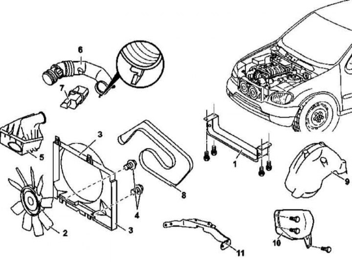
Preparing to remove the cylinder heads of the 112 and 113 series engines
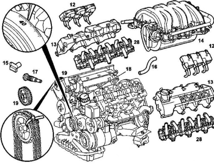
Preparing to remove the cylinder heads of the 112 and 113 series engines
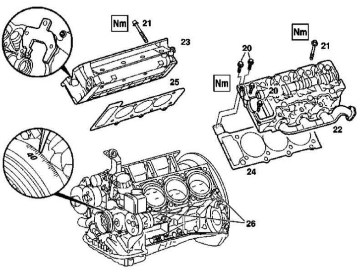
Cylinder head installation parts for 112 and 113 series engines
1. Illustrative material for the removal and installation of the cylinder head of the 112 and 113 series engines is presented in the illustrations, which include all references in the text.
2. Disconnect the negative cable from the battery.
3. Drive the car onto the lift.
4. On models equipped with engine 113.942 (ML 430) remove the air baffle (1).
5. Empty the cooling system (see chapter Ongoing care and maintenance).
6. Remove the power unit cover.
7. On all models except ML 55 AMG and ML 500, remove the viscous fan, then remove the fan shroud.
8. On ML 55 AMG and ML 500 models, remove the electric cooling fan assembly.
9. Install the A/C radiator/condenser shield.
10. Remove the air cleaner (7).
11. Remove the air sleeve (6) with resonator chamber (7).
12. Relieve the pressure in the supply system (see chapter Relieving pressure in the fuel system of a gasoline engine) and disconnect the fuel line from the fuel line.
13. Remove ignition coils (12).
14. Remove cylinder head covers (13).
15. Remove the CMP sensor (15).
16. Auxiliary drive belt.
17. Remove the line of the cooling path (16) on the left cylinder head.
18. Remove the wheel arch locker (9).
19. Remove deflector (10) (models with 113 series engines).
20. Remove the support bracket for the exhaust system (11).
21. Disconnect the exhaust pipes from the exhaust manifolds.
22. Turning the crankshaft in the normal direction, bring the piston of the first cylinder to a position of 40°after TDC, in which there is no risk of pistons colliding with valves when turning the camshafts.
23. Remove chain tensioner (17) (see Section Removal and installation of timing drive components).
24. Remove the oil filter housing (18) complete with liquid heat exchanger (models with 113 series engines).
25. Turn out bolts of fastening of sprockets of camshafts (19).
26. Remove bridges of covers of camshafts (28).
27. Remove the bolts securing the cylinder head to the timing cover (20).
28. Release in several steps, then remove the head bolts (21).
29. Remove the cylinder head.
30. By inspection, identify the version of the head gasket.
31. Examine the condition of the mounting bolts (21).
32. Thoroughly clean the mating surfaces of the heads and block, completely removing all traces of the old gasket material from them.
33. Clean the threaded holes for the mounting bolts.
34. Installation is carried out in the reverse order to the dismantling of the components.
Note. If caverns are found on the mating surfaces of the heads and block, the gasket is installed on the heads using a sealant.
35. Finally, clear the OBD processor memory.