



Contents: Removal ↡ Diesel Engine Cars ↡
Since this procedure requires some experience, only the most important recommendations for a specialist with such experience are presented below.
The given procedure for removing and installing the cylinder head is given using the example of cars with gasoline engines. The features of removing and installing the cylinder head in diesel engines are described at the end of the chapter.
Removal and installation of the head is carried out without dismantling the engine from the engine compartment.
Removal
1. Disconnect the negative (-) wire terminal from the battery terminal with the ignition off.
Attention! When disconnecting the battery from a radio with an access code that prevents its unauthorized use, the specified code is deleted, as well as the settings on the radio station. Therefore, before disconnecting the battery, make sure that the code is written down and can be re-entered into the radio after connecting the battery. If the code is unknown to the car owner, then only a specialized workshop or its manufacturer can put the radio into operation.
2. Drain the coolant from the cylinder block cooling jacket.
3. Remove the cylinder head cover, see the relevant chapter.
4. Remove the ignition coil assembly, see the relevant chapter.
5. Disconnect the inlet pipe from the exhaust manifold.
6. Vehicles with air pump: Remove the air shut-off valve.
7. Remove the thermostat, see the relevant chapter.
8. Set the piston of cylinder No.1 to the TDC position. Cylinder No.1 is located near the V-belt.
To set the cylinder piston to TDC, turn the engine crankshaft so that the TDC mark on the belt pulley is aligned with the mark on the timing chain cover.
In this position of the piston of cylinder No.1, the camshaft cams should be facing away from the valves.
To turn the crankshaft, remove the right front wheel and mudguard. Insert a long 17 mm Allen key (insert) through the hole in the mudguard, for example HAZET-986-17, securing it to an extension handle, and place it on the head of the central bolt of the belt pulley on the crankshaft.
9. Mark the position of the camshaft drive sprocket and camshaft drive chain by drawing a line along the chain and sprocket with a marker.
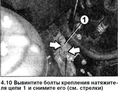
10. Unscrew the chain tensioner mounting bolts 1 and remove it (see arrows in the illustration).
11. Remove the sprocket from the camshaft. When unscrewing the sprocket mounting bolts, hold the shaft by the belt to prevent it from turning.
12. Remove the drive chain from the camshaft sprocket.
13. Support the engine from below with a garage lift and place a wooden block on it.
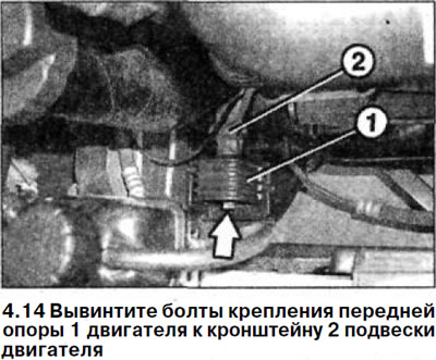
14. Unscrew the bolts securing the front support 1 of the engine to the bracket 2 of the engine mount (see illustration).
15. Remove both socket head bolts from the chain housing.
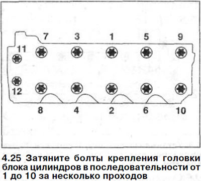
16. Loosen all cylinder head mounting bolts in several passes on a cooled engine, acting in the reverse order of their tightening (see illustration 4.25), and then completely unscrew the bolts.
17. Measure the length of the cylinder head mounting bolts.
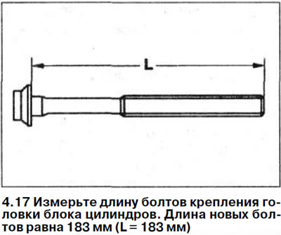
The length of the new bolts is 183 mm (L = 183 mm) (see illustration). With each tightening, the bolts are stretched in length and this elongation is maintained. If the length of the bolts is 186 mm or more, they must be replaced with new ones. It is recommended to install only new bolts after each removal of the cylinder head.
18. Remove the head from the cylinder block using the help of an assistant.
Installation of the cylinder head is performed in the reverse order of removal.
19. Clean the mating surfaces of the cylinder head and block.
20. Inspect the cylinder head and make sure it is not warped or cracked.
21. Clean the holes for the cylinder head mounting bolts.
22. Apply a sealant such as Loctite 5900 to the bridge between the cylinder head and the timing cover.
Attention! After applying the sealant, within 10 minutes, lay the sealing gasket and install the cylinder head.
23. Place a new sealing gasket on the cylinder block.
24. Install the cylinder head into place.
The cylinder head position is centered by dowel pins in the cylinder block. When installing the head, make sure that the head is seated on the dowel pins.
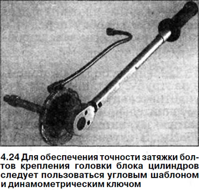
Attention! Tightening the cylinder head bolts should be done with special care. Before tightening, check the accuracy of the torque wrench. To make the work easier, you can use an angle template, for example, HAZET 6690. In order to avoid unnecessary loads on the torque wrench, turn it to the required angle with a regular wrench (see illustration).
Attention! If you do not have an angle template, you must calculate the bolt rotation angle. To do this, place the wrench handle on the angle template along the engine and turn it in one continuous motion until the handle is perpendicular to the engine.
25. Tighten the cylinder head bolts in sequence from 1 to 10 in several passes (see illustration).
- 1st pass: Tighten the bolts with a torque wrench to 35 Nm.
- 2nd pass: Tighten the bolts 90° further with a wrench.
- 3rd pass: Tighten the bolts 90° further with a wrench.
26. Tighten the mounting bolts 11 and 12, which secure the cylinder head to the timing cover, applying a force of 20 Nm (see illustration 4.25).
27. Install the front engine mount and screw it to the engine bracket with a torque of 55 Nm (see illustration 14.2).
28. Lower the garage lift and remove the wooden block.
29. Check the position of the camshaft. When the piston of cylinder No.1 is located, the mark on the camshaft flange should be located in the center of the marking on the camshaft bearing cap.
Make appropriate adjustments if necessary.
Caution! Before turning the camshaft, turn the crankshaft so that it is at an angle of 30° after TDC to avoid collision of the valves and piston crowns and damage to them.
30. Install the sprocket on the camshaft and secure it with a new socket head bolt to a tightening torque of 20 Nm. Then tighten the bolt by 60°.
31. Position the camshaft drive chain so that the marks made on the chain and on the sprocket before removal match.
32. Check the original position of the camshaft again.
33. Install the chain tensioner, replacing its old gasket with a new one.
Attention! Pay attention to the correct installation, as the hole is slightly offset from the center.
34. Tighten the chain tensioner mounting bolts. The tightening torque is 8 Nm.
35. Install the exhaust manifold on the cylinder head pins, first installing a new sealing gasket. Before installing the manifold, inspect the threaded pins and replace them if necessary. install a new gasket, screw the exhaust manifold to the cylinder head. Screw the flange nuts onto the pins and tighten them to 40 Nm.
36. Check the engine oil level.
37. Warm up the engine to operating temperature and check the tightness of all connections. The tightness of the cooling system is checked using a device for bleeding it only after warming up the engine to operating temperature.
Caution! The cylinder head gasket becomes airtight only after the engine has warmed up to operating temperature and the gasket has swollen.
Diesel Engine Cars
The procedure for removing and installing the cylinder head is similar to dismantling and installing it on cars with gasoline engines, except that diesel engines require removing and installing the injectors, camshafts and balancers. The tightening torques for the main threaded connections are also given below.
38. Measure the length of the M-12 cylinder head bolts. The length of the new bolts is 186 mm. With each tightening, the bolts are stretched in length and this elongation is maintained. If the length of the bolts has reached 188 mm or more, they must be replaced with new ones.
39. Lubricate the threads and the mating surface of the heads of the new bolts.
40. Tighten the cylinder head bolts in the same sequence as in cars with petrol engines, i.e. from 1 to 10 in several passes.
- 1st pass: Tighten the bolts with a torque wrench to 60 Nm.
- 2nd pass: Tighten the bolts with a wrench by 180°.
41. Tighten the cylinder head bolts to the timing cover with a torque of 20 Nm.
42. Set the piston of cylinder No.1 to TDC and fix the camshafts in this position by inserting two 6 mm diameter cylindrical pins into the holes on the drive sprockets of the shafts.
When the crankshaft is at TDC of the piston of cylinder No.1, the pins should be in contact with the cylinder head.
Tightening torques for threaded connections:
- exhaust manifold flange nut - 21 Nm
- exhaust manifold mounting studs (fingers) - 11 Nm
- sprocket to camshaft - 18 Nm
- camshaft bearing cap to cylinder head - 9 Nm
- front/rear timing cover - 9 Nm
- timing chain tensioner - 89 Nm