
To remove the engine, it is necessary to dismantle all units mounted on the front beam.
Due to the fact that the implementation of this set of works on the engine requires a certain experience, it is recommended to entrust them to the workshop.
For this reason, the chapters in this section only show the basic steps to be taken while working on the engine.
The above procedure for removing and installing the power unit is given on the example of cars with gasoline engines. Features of removal and installation of diesel engines are stated at the end of the chapter.
Removing
1. Cars with automatic transmission. Drain the gearbox oil.
2. Screw in the drain plug after draining the gear oil is complete, installing a new o-ring on the plug. Plug tightening torque 22 Nm.
3. Drain the coolant from the radiator and engine block.
4. Disconnect the wire terminal «masses» (-) from the battery terminal by turning off the ignition.
Attention! Disconnecting the battery from a radio with an anti-tampering access code will delete the specified code, as well as the settings on the radio. Therefore, before disconnecting the battery, make sure that the code is recorded and that it can be re-entered into the radio after the battery is connected. If the code is unknown to the owner of the car, then only a specialized workshop or its manufacturer can put the radio into operation.
5. Wring out the locking lever, remove the windscreen washer tank from the supports and hang it up.
Attention! On vehicles with a heated washer reservoir, first disconnect the coolant hoses.
6. Disconnect the ground wire (-) on the front engine mount on the right side.
7. Remove the air intake, air intake hose, and on vehicles with 1.6 / 1.9 liter engines, also the resonator.
8. Remove the low pressure hose from the intake manifold.
9. Disconnect the multi-pin plug from the engine control unit by lifting the clamp up and unlocking it.
10. Disconnect the fuel line from the distribution line and plug it with a suitable plug.
11. Disconnect the low pressure hoses from the canister valve and intake manifold and set them aside from the work area.
12. Disconnect the cooling system hoses from the radiator and expansion tank.
13. Vehicles manufactured since 6/99 with a separate expansion tank. Squeeze out the locking bracket and remove the tank.
14. Remove a hose of a cooling liquid from a branch pipe on the thermostat case.
15. Cars with automatic transmission. Disconnect the oil lines from the oil cooler and plug them with suitable plugs. The oil cooler is integrated into the radiator of the engine cooling system.
16. Disconnect the heater inlet and outlet hoses.
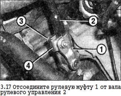
17. Disconnect the steering clutch 1 from the steering shaft 2. To do this, unscrew the clamping bolt 3 with a head for a multi-sided socket wrench and remove the stop 4 (see illustration).
18. Open the cover of the junction box of wires on the left side member of the frame and disconnect the positive wire and power steering power wire.
19. Cars with a manual transmission. Turn the jam nuts counterclockwise to loosen them and disconnect the shift links from the ball heads.
20. Cars with automatic clutch. Disconnect the connectors on the gearbox, release the wiring harness from the holder and set it aside from the work area.
21. Disconnect the hose from the air pump, if any.
22. Disconnect the top support of both depreciation racks.
23. Unscrew both calipers from the steering knuckles and secure them with wire under the fenders without removing the brake pads or disconnecting the brake hoses.
24. The brake mechanism of the right wheel. Disconnect the brake pad wear sensor and wheel speed sensor connector.
25. Disconnect the exhaust pipe from the catalytic converter.
26. Disconnect the flange at the junction of the front pipe and the catalyst. Depending on the car model, the flange can be bolted or the junction of the exhaust pipe and the catalyst is connected with a clamping collar.
27. Engine with two lambda probes. Release the connecting wire of the lambda probe fixed on the bottom and disconnect the plug.
28. Feed down the connecting hose and remove it from the gearbox, after removing the safety clip. Plug the hose opening with a suitable plug.
29. Cars with air conditioning. Loosen the ribbed belt and remove it from the A/C compressor pulley.
30. Cars with air conditioning. Unscrew the compressor mounting bolts, and, without disconnecting the hoses and power wires from it, fix it to the bottom with wire.
31. Support the front axle beam with a garage jack, placing it on a wooden block.
32. Unscrew bolts of fastening of a spacer by which the beam is connected with the bottom.
33. Unscrew the bolts securing the left and right fender liner to the bottom and move them down to gain access to the mounting bolts of the front axle beam.
34. Unscrew eight bolts of fastening of a beam of the forward bridge. The bolts have heads for multifaceted socket wrench.
35. Lower the engine down on the front axle beam to gain access to the starter and alternator.
36. Cars with automatic transmission. Disconnect the shift rod from the gearbox. To do this, disconnect the linkage mount on the box and remove it from the seat, and also disconnect the plug on the gearbox.
37. Disconnect the ground wire (-) from the oil pan together with the holder.
38. Disconnect the power wires from the starter.
39. Disconnect the power wires from the generator.
40. Lower the power block on the beam down, observing the precautions. Have an assistant drive the engine when lowering it.
Removing the engine from the front axle beam
41. Raise the engine and transmission with a suitable lifting device (hoist, etc.), to relieve the engine mounts.
Attention! To lift the engine, run three chains on the right and left sides of the engine and oil pan. Chains should be as vertical as possible, which is possible with the help of an appropriate frame.
42. Remove the shoulder bolts that secure the engine mounts.
43. Using a suitable screwdriver, press the left axle shaft out of the gearbox.
44. Unscrew bolts of fastening of the basic bearing of an intermediate shaft to the block of cylinders.
45. Using a suitable screwdriver, wring out the intermediate shaft of the right axle shaft from the gearbox.
46. Carefully lift the engine together with the gearbox and carefully remove the shank of the left axle shaft, as well as the intermediate shaft, from the gearbox. Check the condition of the circlips on the drive shafts and replace them with new ones if damaged.
47. Unscrew bolts of fastening of an arm of the catalyst to a transmission.
48. Unscrew the bolts that connect the engine and gearbox.
49. Remove a starter and wring out a transmission from the engine. Do not lose the centering sleeves.
Installation
The engine is installed on the front axle beam in the reverse order.
50. Lower the power block down and carefully insert the left drive shaft and intermediate shaft shanks into the splines on the gearbox until fully engaged.
Tightening torques for threaded connections:
- starter to gearbox - 20 Nm
- engine and gearbox - 20 Nm
- engine mounts suspension bracket matte - 55 Nm
- support bearing of the intermediate shaft to the engine - 20 Nm
Installing the engine together with the front axle beam
Installation is made in sequence, return to removal. In doing so, you must also do the following:
51. Connect the power wires to the starter and generator.
52. Raise the engine together with the front axle beam and guide them in such a way that the guides on the front axle beams fit exactly into the holes on the side members.
53. Tighten all of the multi-faceted socket head axle beam mounting bolts first, then tighten the rest.
Tightening torques:
- M12 socket head bolt - 120 Nm
- socket head bolt M10 - 60 Nm
54. Insert the connecting hose with a new sealing ring into the gearbox and fix it by sliding the stopper from the side.
55. Fasten the intake pipe with bolts, installing a new gasket, on the catalytic converter connecting flange and tighten them with a torque of 25 Nm. Replace cap nut if damaged. If the front pipe is connected to the catalytic converter with a clamp, install the clamp.
56. Screw the brake calipers with new bolts and tighten them with a tightening torque of 115 Nm.
57. Fix the upper supports of both suspension struts on the mudguards. Tighten their fastening bolts with a torque of 40 Nm.
58. Cars with a manual transmission. After connecting the gear shift rods, check the reliability of their fastening.
59. Attach the steering sleeve to the steering shaft by screwing on a new self-locking flanged nut or installing a new bolt and tighten to 20 Nm.
60. Cars with automatic transmission. Connect the oil line hoses and secure them with a tightening torque of 25 Nm.
61. Connect the multi-pin plug to the engine control unit and fix it with the bracket by pressing it down.
62. Connect the wire terminal «masses» (-) to the battery terminal with the ignition off. Enter the access code supplied with the radio and set the clock.
63. Cars with automatic transmission. Screw in the drain plug with a new seal and tighten the plug to 22 Nm.
64. Fill the gearbox with oil.
65. Remove air from the hydraulic clutch.
66. Fill the cooling system with coolant and check the system for leaks.
Diesel vehicles
67. Remove the front bumper.
68. Remove the charge air cooler and disconnect the charge air hose from the mixer.
69. Disconnect the low pressure hoses from the turbocharger, the exhaust gas recirculation valve, the boost air pressure sensor, and also from the vacuum pump by squeezing the clamp leads.
70. Disconnect the fuel hoses from the fuel filter and plug them with suitable plugs.
Attention! On vehicles manufactured from 03/01, the alternator power cable at terminal D + is not screwed on, but simply inserted.
71. Remove the engine from the front axle beam. Disconnect the wire first «masses» (-), mounted on the bracket of the front left engine mount.