
Preparing to remove the 612 series engine
Preparing to remove the 612 series engine
1. Illustrative material for preparing to remove the engine is presented in the illustrations, which include all references in the text.
2. Open the hood and support it in an upright position.
3. Disconnect the negative cable from the battery.
4. Remove overlays of heads of cylinders.
5. Remove the bottom section of the soundproofing.
6. Empty the cooling system (see chapter Checking the cooling system and frost resistance of the coolant, changing the fluid).
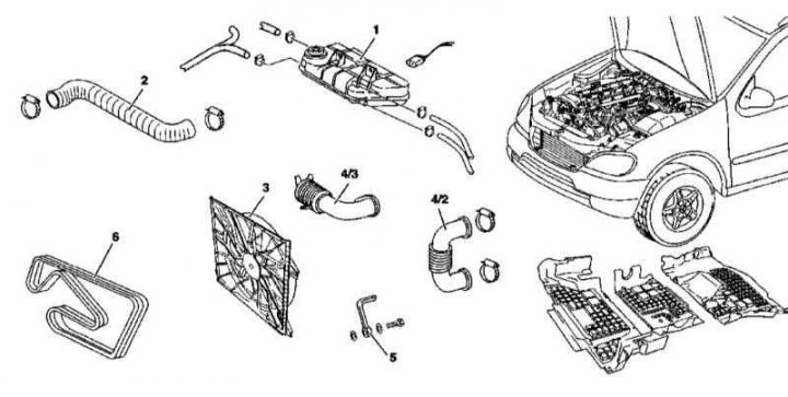
7. Remove the expansion tank of the cooling system (1).
8. Disconnect the hose (2) cooling path from the thermostat housing to the radiator.
9. Remove the air intake (4/3).
10. Remove the air intake sleeve (4/2).
11. Remove the electric fan (3) cooling systems.
12. Install the A/C radiator/compressor shield.
13. Remove the accessory drive belt (6).
14. Pump out the hydraulic fluid from the power steering reservoir (see chapter Filling and «pumping» steering pump).
15. Disconnect the power steering path line (5) from the radiator.
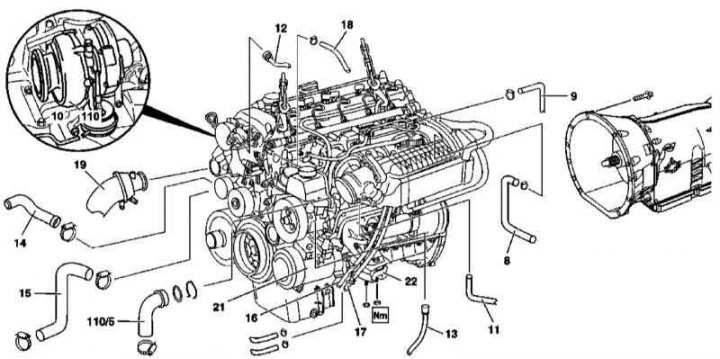
16. Disconnect the power steering path line (13) from the steering pump, - plug the open ends of the hose and suction fitting immediately.
17. Disconnect the vacuum hose (10) from the blower control unit. Also disconnect the vacuum lines (11 and 12), leading to the mixing chamber and vacuum pump.
18. Detach the air sleeve (19) from the turbocharger.
19. Pick up the handset (110/5) air supply to the mixing chamber.
20. Disconnect the pipes of the cooling path (14 and 15) from the water pump.
21. Disconnect the hose (16) fuel cooler.
22. Disconnect the hose (17) low temperature cooler and remove the hose (18), connected to the thermostat housing.
23. Disconnect the fuel supply pipe (8) preheating systems.
24. Disconnect the return pipe from the fuel cooler (9).
25. Disconnect the connector (s) engine wiring.
26. Pick up the phone (19), coming from the turbocharger (110) to the air cooler.
27. Disconnect electroconducting from the K/V compressor.
28. Screw off the A/C compressor (21).
29. Hang the engine on the winch.
30. Turn out bolts from apertures under installation of a prop on a case of transmission.
31. Support the transmission.
32. Turn out bolts of fastening of transmission to the engine.
33. Loosen the spring-loaded joint securing the primary catalytic converter to the main three-function catalytic converter (TWC).
34. Release the fastening elements of the front support suspension of the power unit (22) to the car frame.
35. Separate the engine from the transmission and carefully remove it from the engine compartment of the car.
36. Installation is carried out in the reverse order.
M628
Preparing to remove the 628 series engine
Preparing to remove the 628 series engine
1. Illustrative material for preparing to remove the engine is presented in the illustrations, which include all references in the text.
2. Open the hood and support it in an upright position.
3. Disconnect the negative cable from the battery.
4. Lift the power package cover.
5. Discharge the air conditioning system in a car service workshop.
6. Remove the left and right headlights (see chapter Body).
7. Remove the upper frame cross member (see chapter Body).
8. Remove the washer fluid reservoir (see chapter Body).
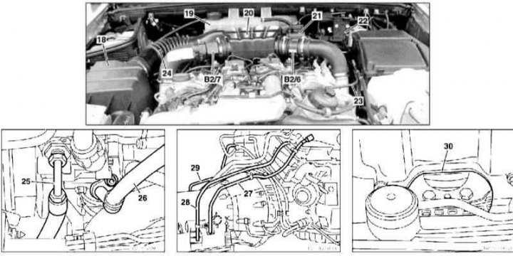
9. Remove the air cleaner assembly (18).
10. Having previously pumped out the hydraulic fluid, remove the reservoir (21) steering pump from the base plate of the intake air distribution sleeve.
11. Remove the left front wheel.
12. Remove the wheel arch protection locker.
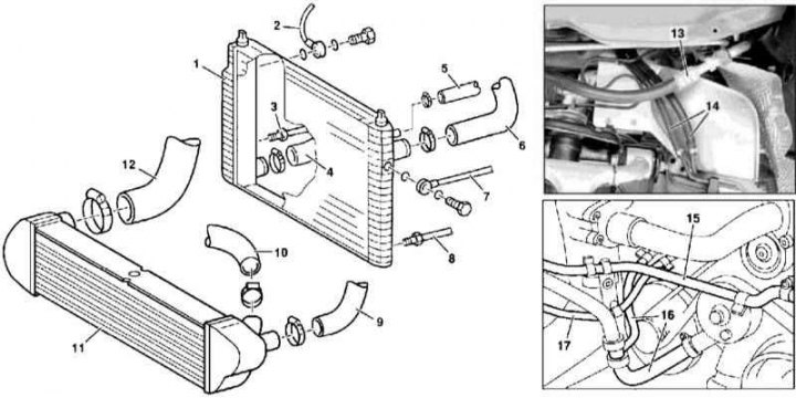
13. Working through the wheel arch, separate the refrigerant line (13) from the A/C compressor.
14. Also through the arch, disconnect the fuel lines (14).
15. Remove the bottom section of a noise isolation.
16. Empty the cooling system (see chapter Checking the cooling system and frost resistance of the coolant, changing the fluid).
17. Disconnect from cooler (11) air hoses (9 and 10) right and left turbochargers, and boost air sleeve (12).
18. Loosen the primary catalytic converter clamps on the left and right turbochargers.
19. Turn out bolts of fastening of a dome of transmission to the engine (except for the lower).
20. Give nuts of the left and right support of a suspension bracket of the power unit.
21. Remove the cover (30) service window and unscrew the bolts securing the rotation converter to the engine start drive disk equipped with a gear rim.
22. Separate the left and right drain hoses from the transmission case (28 and 29).
23. Disconnect from the radiator (1) ventilation (5) and pitchers (4 and 6) hoses.
24. Disconnect from a radiator of a line of a path of cooling ATF (2 and 3).
25. Disconnect from the radiator lines of the power steering fluid cooling path (7 and 8).
26. Remove the electric cooling fan (see chapter Cooling, heating and air conditioning systems).
27. Install the A/C radiator/compressor shield.
28. Disconnect the hoses (15 and 17) low temperature cooler.
29. Disconnect the heater return hose (16).
30. Disconnect the MAF sensor wiring connectors (B2/6 and B2/7).
31. Remove the air distributor (20) with air cleaner inlet sleeve (24).
32. Remove the expansion tank of the cooling system (19).
33. Remove the heat exchanger supply hose on the left side of the bulkhead of the engine compartment.
34. Remove the circulation pump of the cooling system (additional equipment) from the battery shield and, without disconnecting the hoses, take it to the side.
35. Release the fasteners and remove the filler tube (27) ATF from the cylinder head cover.
36. Separate the shutoff valve inlet port vacuum line from the fuse and relay mounting block (23) and ventilation hose of the cooling system.
37. Disconnect the check valve inlet port vacuum line (23) from the brake booster servo.
38. Disconnect the A/C refrigeration line from the compressor (26).
39. Disconnect the pressure line from the steering pump (25).
40. Disconnect the drive cable from the position sensor (22).
41. Remove position sensor (22) from the bulkhead.
42. Disconnect the connector (s) engine wiring.
43. Hang the engine on the winch, fully unloading the front suspension mounts of the power unit.
44. Support the transmission.
45. Turn out the bottom bolts of fastening of a dome of transmission to the engine.
46. Pulling the engine forward, separate it from the transmission, then carefully remove it from the engine compartment.
47. Installation is carried out in the reverse order.
48. Pour fresh coolant into the cooling system, in the conditions of service stations, charge the A/C system. Check ATF level, correct if necessary (see chapter Replacing and checking the ATF level, replacing the AT filter).
49. Finally, connect the STAR DIAGNOSIS reader to the DLC diagnostic connector and poll the processor memory for fault codes (DTC). After performing the necessary fixes, clear the system memory.