
Depending on the date of manufacture and engine equipment, wiring harnesses, fuel lines, vacuum hoses, as well as hoses of the cooling system in the engine compartment have different wiring. Since this manual cannot cover all configuration options in detail, we suggest marking the removed parts with paint or tags so that there are no difficulties during installation.
Note. The procedure for performing operations for removing and installing a 6-cylinder in-line engine is similar to that given for a 4-cylinder.
Removing
1. Place the hood in an upright position by opening the hood, pressing it in and holding it in that position. Press the locking lever with the inscription «PRESS» near the right hinge and release the hood. Gas-filled shock absorbers will bring it to a vertical position.
2. Remove a casing of a motor compartment from below.
For models manufactured from 06.1995 to 06.1996 equipped with air conditioning:
3. Remove the viscous coupling of the cooling fan. In this case, it should be noted that the fastening parts have a left-hand thread.
For all models:
4. Drain the coolant and remove the radiator.
Attention! On vehicles equipped with air conditioning, after removing the radiator, it is necessary to protect the condenser with a plate 400 x 680 x 1 mm, which can be made independently from tin and fixed with mounting brackets.
5. Disconnect the connector from the mass air flow meter.
6. Take out a cross pipe together with the top cover of the air filter and a measuring instrument of the mass expense of air.
7. Disconnect a wire from the negative plug of the storage battery.
Attention! At the same time, the codes of the anti-theft system, radio, radio are erased from the memory of electronic devices. Subsequently, they need to be restored.
8. Remove the control box cover.
9. Disconnect the control unit connector by lifting the clips up.
10. Disconnect the surge protection connector.
11. Disconnect wires from the generator.
12. Disconnect a contact socket of the gauge of concentration of oxygen.
13. Disconnect the tire «masses» from the engine.
For vehicles with automatic transmission (AKP):
14. Disconnect a contact socket in a motor compartment ahead at the left. In this case, unscrew the fastener and lift the reservoir with the windshield washer fluid.
For all models:
15. Disconnect the wire connected to the contact outside the body «30», located in the driver's footwell.
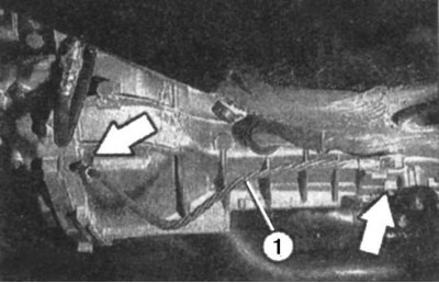
Pic. 5.10. Wire connecting the engine to the body: 1 - wire
16. Disconnect the wire fastener 1 (pic. 5.10) «masses», connecting the body to the engine.
For models with air conditioning:
17. Disconnect the connector from the compressor.
For all models:
18. If the transmission is disconnected from the engine, remove the starter.
19. Disconnect the vacuum hose from the absorber valve.
20. Disconnect the accelerator link.
21. Briefly open the fuel tank cap to relieve excess fuel vapor pressure.
Attention! Due to the risk of ignition, do not use open flames, heated objects, do not smoke. Gasoline vapors are poisonous, so make sure your work area is well ventilated. Wear safety goggles as the fuel system is under pressure. When disconnecting its elements, fuel can be ejected.
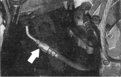
22. Mark the fuel lines with tags or adhesive tape and disconnect them, first plugging the holes and pinching the hoses with clamps against fuel leakage. Remove spilled fuel with a rag.
23. Disconnect the vacuum lines from the intake manifold by unscrewing the union nuts.
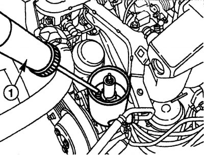
Pic. 5.11. Removing the working fluid from the power steering reservoir: 1 - syringe
24. Using a syringe, pump out 1 working fluid from the power steering reservoir (pic. 5.11), then disconnect the hoses by plugging the holes with process plugs.
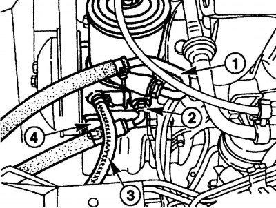
Pic. 5.12. Disconnecting the power steering hoses: 1 - return hose; 2, 3 – high pressure hose; 4 - suction oil pipeline
25. Disconnect return hose 1 (pic. 5.12) and high pressure hose 2 from the power steering pump.
For vehicles with ride height control:
26. Disconnect the additional high-pressure hose 3 and the suction oil line 4, first loosening the clamps and moving them.
For all models:
27. Disconnect the cooling system hoses from the rear cylinder head and from the coolant pump, first loosen the clamps and move them.
Attention! Do not open the air conditioning circuit - skin contact with refrigerant may cause local frostbite.
For models with air conditioning:
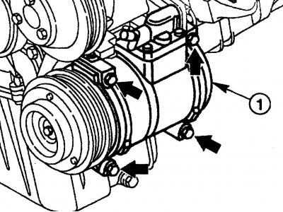
Pic. 5.13. Removing the mounting of the air conditioning compressor: 1 - compressor
28. Remove the bolts (pic. 5.13, arrows) fixing the compressor 1, after which, without disconnecting the hoses, hang it to the body with a wire.
For all models:
29. Drain the coolant from the cylinder block into an appropriate container by unscrewing the drain plug. Close the plug after draining.
30. Disconnect the control rods from the gearbox.
Pic. 5.14. Disconnecting the pipeline from the clutch slave cylinder
31. Disconnect the pipeline from the clutch slave cylinder (pic. 5.14).
32. Remove the exhaust system.
33. Disconnect the cardan shaft from the gearbox.
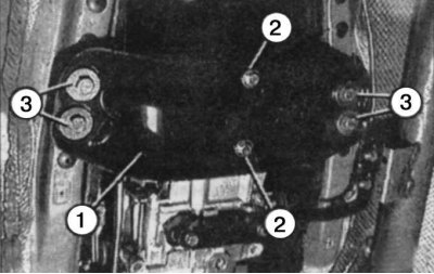
Pic. 5.15. Rear transverse beam of the power unit: 1 - beam; 2, 3 - bolts
34. Remove the rear cross beam 1 (pic. 5.15) power unit together with the support.
35. Turn away bolts of fastening of support of the engine to a body and a cross beam of a forward suspension bracket.
36. If the gearbox is disconnected from the engine, unscrew the lower bolts securing the gearbox to the engine.
37. Attach the hoist straps to the engine lugs and lift the power package until the cables are taut.
38. Turn away the top bolts of fastening of a transmission to the engine.
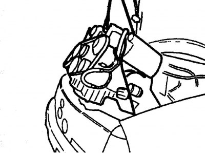
Pic. 5.16. Lifting the power unit
39. Press the engine from the gearbox with the mount and lift it up. Ensure that the power unit is tilted no more than 45° (pic. 5.16).
Attention! When lifting the power unit, be careful not to damage the bodywork. Pay special attention to the rear eyelet and oil filter.
40. Remove the engine from the car, disconnect a transmission.
Checking the technical condition of parts
Make sure that there are no cracks or breaks on the rubber mounts of the power unit, coolant hoses, pipelines.
The ball bearing located in the crankshaft should rotate easily and without jamming.
Make sure that the clutch release bearing rotates easily and has no binding during axial movement.
Check the thickness of the friction linings of the clutch disc.
Installation
41. Connect a transmission to the engine if it has been removed.
42. Install the power unit in the engine compartment through the top, making sure that when lowering, the parts of the power unit and the body are not damaged.
43. Connect the gearbox to the intermediate flange of the engine by tightening the mounting bolts with torques: M10x40 - 55 Nm, M10x45 - 55 Nm, M10x90 - 45 Nm.
44. Connect wire 1 «masses» (pic. 5.10).
45. Install the bolts of the front supports of the power unit and tighten them by hand.
46. Wrap bolts of fastening of a back support the following moments:
- bolts 2 (pic. 5.15):
- on engines of series 111 and 104 - 25 Nm;
- on the 112 series engine - 30 Nm;
- bolts 3 for fastening the rear cross member to the body - 40 Nm;
- bolts and nuts for fastening the rear support to the gearbox - 40 N·m;
47. Wrap bolts of fastening of a forward support the following moments:
- bolts of fastening to a beam of a forward suspension bracket:
- on engines of series 111 and 104 - 55 Nm;
- on the 112 series engine - 35 Nm;
- engine block mounting bolts:
- on engines of series 111 and 104 - 25 Nm;
- on the 112 series engine - 20 Nm;
- heat shield mounting bolt - 10 Nm;
48. Connect the cardan shaft to the gearbox.
49. Install the starter (if the engine was removed without a gearbox).
50. Connect the wire to the motor «masses», coming from the body.
51. Connect the gearbox to the control mechanism.
52. Connect the clutch slave cylinder to the pipeline, then bleed the air from the clutch hydraulic actuator.
53. Establish details of system of release of the fulfilled gases.
For models with air conditioning:
54. Install compressor 1 (see fig. 5.13), tightening the mounting bolts to a torque of 25 Nm, and remove the protective plate for the condenser.
For all models:
55. Install the accessory drive belt.
56. Install the radiator.
57. Install the cooling system hoses and securely fasten them with clamps.
For models manufactured from 06.1995 to 06.1996 equipped with air conditioning:
58. Install the viscous coupling of the cooling fan. In this case, it should be noted that the fastening parts have a left-hand thread.
For all models:
59. Establish from below a guard of a motor compartment.
60. Lower the car.
61. Attach return hose 1 (see fig. 5.12) and high pressure hose 2 to the power steering pump.
For vehicles with ride height control:
62. In addition to the previous operation - connect the high pressure hose 3 and the suction oil line 4.
For all models:
63. Connect fuel lines.
64. Connect the vacuum hoses to the engine.
65. Install the control box cover.
For models with automatic transmission:
66. Connect piping to valve block.
For all models:
67. Put the vacuum hose on the absorber valve.
68. Install the air filter cross tube, MAF sensor and air filter top.
69. Connect the connector to the mass air flow sensor.
70. Check the level of brake fluid in the tank, if necessary, replenish its volume to normal and remove air from the brake system.
71. Pour working fluid into the power steering reservoir and bleed air from the system.
72. Pour coolant into the expansion tank of the cooling system.
73. Check the oil level in the engine and gearbox, top up if necessary.
74. Connect the wire to the negative battery terminal.
75. Start the engine and warm it up to operating temperature, check the coolant level in the cooling system, as well as the tightness of the hose connections.
76. Close the hood by pressing the lever near the right hood hinge.
77. Set the clock.
78. Enter the codes for the anti-theft system and the radio.
79. Read possible codes of malfunctions of the engine and eliminate these malfunctions.