
Checking the technical condition of the auxiliary drive belt
"30,000 km 2 years"
1. Turn off the ignition.
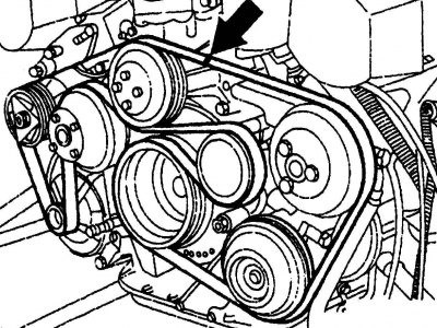
Pic. 5.4. Checking the technical condition of the auxiliary drive belt
2. Mark the belt with chalk in a clearly visible place (pic. 5.4, arrow).
3. Place the shift lever in neutral position.
4. Brake the vehicle with the parking brake.
5. Turn the engine with a socket wrench until chalk markings appear on the belt.
Attention! Rotate the engine only clockwise.
6. Rotate the crankshaft a few more times. Only in this way will you be able to view the entire belt. Often there is only one, but a very deep cut, which is not visible during inspection, because in this place the belt lies on the pulley.
7. Check the outer surface of the belt.
8. The belt should be replaced if you find the following defects:
- uneven wear marks on the edges of the belt;
- porous surface or «fringe»;
- cuts;
- traces of oil or fat.
Removing, installing and tensioning the accessory drive belt
4-cylinder in-line engine
Removing
For models with automatic control of the heating or air conditioning system before 08.1996.:
1. Remove the viscous fan clutch.
For all models:
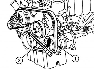
Pic. 5.5. Changing the tension of the accessory drive belt: 1 - belt; 2 - key
2. Install the wrench 2 on the tension roller bolt (pic. 5.5) with a Torx socket E10 and turn the wrench anti-clockwise, loosen the tension of the belt 1.
3. Remove the belt.
Attention! Do not tilt the tension lever by the tension roller mounting nut.
Installation
4. Check pulley profiles and tensioner for damage and dirt. Clean or replace parts as needed.
5. Check tensioner bearings and pulley ribs for chipping.
6. Check the condition of the belt. If there is contamination of the streams, fraying, transverse cracks or breaks, the belt must be replaced.
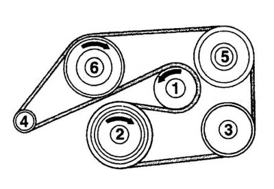
Pic. 5.6. Installing the accessory drive belt on a 4-cylinder in-line engine: 1 - tension roller; 2 - crankshaft; 3 - compressor (air conditioning system); 4 – alternating current generator; 5 – the pump of the amplifier of a steering; 6 - coolant pump
7. Put the belt on the pulleys, starting with the tension roller 1 (pic. 5.6) and further according to the numbering shown in the diagram.
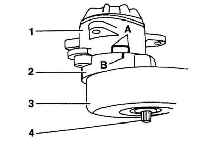
Pic. 5.7. Tension roller installation: 1 - holder; 2 - tension lever; 3 - tension roller; 4 - bolt Torx E10
8. Release tension roller 3 (pic. 5.7). Label «IN» must be located in the working area «A». If the mark goes beyond this zone, it indicates that the belt length does not match for this engine or the tensioner malfunctions.
9. Check the position of the belt on the pulleys.
10. Install the viscous fan clutch.
6-cylinder in-line engine (additional information)
Attention! Since the engine is equipped with two types of tension rollers - 92 mm and 80 mm in diameter, belts of different lengths are required. When installing a tensioner pulley with a diameter of 80 mm, the belt is 20 mm shorter than when installing a pulley with a diameter of 92 mm.
Removing
1. Remove the fan shroud.
2. Install a SW15 socket wrench on the idler nut and turn the wrench counterclockwise to loosen the belt tension.
3. Remove the belt.
Installation
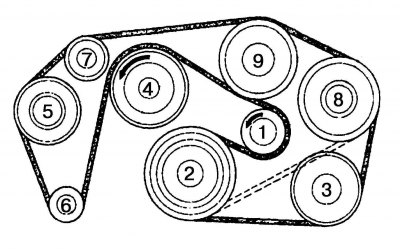
Pic. 5.8. Installing the accessory drive belt on a 6-cylinder in-line engine: 1 - tension roller; 2 - crankshaft; 3 - compressor (air conditioning system); 4 - fan; 5 - air pump; 6 – alternating current generator; 7 - upper guide roller; 8 – the pump of the amplifier of a steering; 9 - coolant pump
4. Put the belt on the pulleys, starting with the tension roller 1 (pic. 5.8) and further according to the numbering shown in the diagram.
5. Loosen the tension roller by turning the wrench clockwise. Put on the belt completely.
6. Check the position of the belt on the pulleys.
7. Insert fan shroud ring, turn and lock.
6-cylinder V-engine (additional information)
Removing
1. Remove the viscous fan.
2. Remove the fan shroud.
3. Loosen the belt tension by installing a Torx socket wrench on the idler pulley bolt and turning it counterclockwise.
4. Remove the belt.
Installation
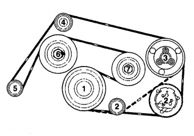
Pic. 5.9. Installing the accessory drive belt on a 6-cylinder V-engine M112: 1 - crankshaft; 2, 4 - guide roller; 3 – the pump of the amplifier of a steering; 5 - generator; 6 - coolant pump / fan; 7 - tension roller
5. Slide the belt over the pulleys, starting with pulley 1 (pic. 5.9) crankshaft and further according to the numbering shown in the diagram.
6. Loosen the tension roller by turning the wrench clockwise. Put on the belt completely.
7. Check the position of the belt on the pulleys.
8. Install the fan shroud.
9. Install a viscous fan.