
Drive Belt Check - Basics
1. Due to their application and design, belts have a limited service life and. Belts should be checked periodically to avoid problems.
2. The number of belts is determined by the number of additional systems installed (aggregates). Belt driven water pump, alternator, power steering/suspension hydraulic pump, air conditioning compressor and air pump
3. To improve belt inspection access, if desired, remove the viscous cooling fan and shroud as described in Chapter 3.
4. With the engine off, using your fingers (and, if necessary, a flashlight) move along the belts, checking for cracks and delamination of the belt. Check also the fraying of the belt and the icing that gives the belt a shiny look. Both sides of the belts should be checked, which can be done by turning the belt. If necessary, turn the crankshaft with a wrench on the crankshaft pulley hub bolt so that the whole belt can be checked.
4 Cylinder Single Belt Engines - Belt Replacement
5. Remove the cooling fan blades and boot as described in Chapter 3.
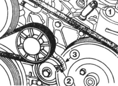
6. Loosen the tensioner bolt a quarter-half-turn (if necessary, remove the plastic plug to gain access to the bolt) (see fig. 8.6).
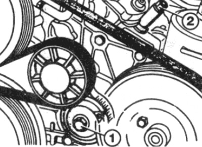
Pic. 8.6. Loosen tensioner bolt (1) and turn the adjusting nut (2) - 4-cylinder engine with single accessory drive belt
7. Loosen the adjusting nut (counterclock-wise), to move the adjuster back and remove the belt from the pulleys.
8. Route the new belt around the pulleys in order, starting with the tensioner pulley (see fig. 8.8, a-c). Make sure the belt is properly seated on the pulleys.
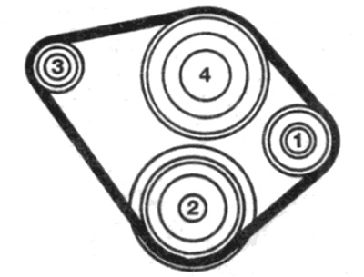
Pic. 8.8, a. Accessory drive belt - 4-cylinder engine without power steering
Install the belt in the following order:
1 tensioner pulley
2 crankshaft pulley
3 Alternator pulley
4 Water pump pulley
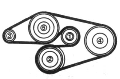
Pic. 8.8b. Accessory drive frame - 4-cylinder engine with power steering, but without air conditioning (one belt)
Install the belt in the following order
1 tensioner pulley
2 crankshaft pulley
3 Alternator pulley
4 Power steering pump pulley
5 Water pump pulley
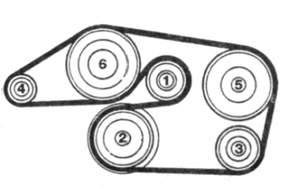
Pic. 8.8, c. Accessory drive belt - 4-cylinder power steering with air conditioning (one belt)
Install the belt in the following order
1 tensioner pulley
2 crankshaft pulley
3 Air conditioning compressor pulley
4 Alternator pulley
5 Power steering pump pulley
6 Water pump pulley
9. Tension the belt as follows.
Models with a graduated scale printed on the tensioner
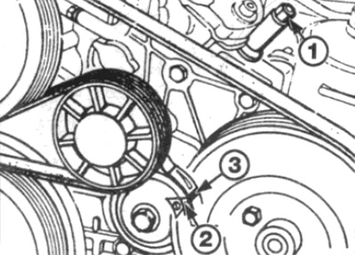
10. On vehicles without power steering, turn the adjusting nut clockwise until the tensioner pointer is aligned with the 5th scale division (on the left side, looking at the scale in front of the engine compartment) (see fig. 8.10).
Pic. 8.10. Turn the adjusting nut (1) until. until the tip of the pointer is aligned with the 5th division of the scale (3) - 4-cylinder engine (one strap)
11. On models equipped with power steering, turn the adjusting nut clockwise until the tip on the pointer is between 8 and 9 divisions on the scale (on the left side, looking at the scale in front of the engine compartment).
12. Tighten the tensioner bolt to the required torque and install the cover (where provided).
13. Install the radiator fan blades and shroud as described in Chapter 3.
Thick Mark Models (and molded triangle) on the tensioner scale
14. Turn the adjusting nut clockwise to align the pointer tip with the thick line (on the thicker edge of the triangle) on the scale (see fig. 8.14).
Pic. 8.14. Turn the adjusting nut (1) to pointer (2) aligned with thick line (3) not shkele - 4-cylinder engine with one belt
15. Tighten the tensioner bolt to the required torque and install the cover (where provided).
16. Install the radiator fan blades and shroud as described in Chapter 3.
4-cylinder engines with multiple belts - belt replacement
Alternator/Water Pump Drive Belt
17. If necessary, to improve access, remove the shields from the bottom of the car, as described in Chapter 11.
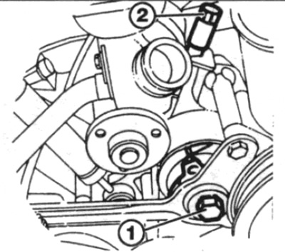
18. Loosen the upper and lower nuts securing the generator and the bolt securing the adjusting lever to the casing of the camshaft drive chain (see fig. 8.18).
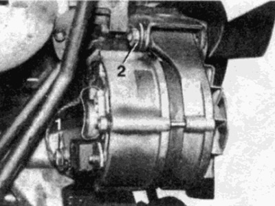
Pic. 8.18. Loosen the top (2) and lower alternator mounting nuts (1) - 4-cylinder engine (multiple drive belts)
19. To move the generator forward towards the engine to remove the belt from the pulleys, turn the adjusting bolt (see fig. 8.19).
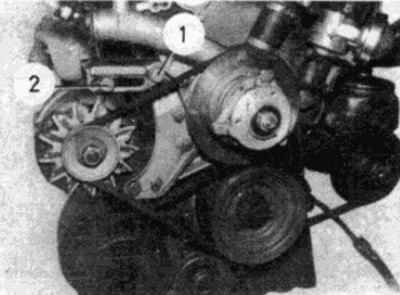
Pic. 8.19. Bolt of the adjusting lever of the generator (1) and adjusting bolt (2) - 4-cylinder engine (multiple drive belts)
20. Route the new belt around the pulleys, then turn the adjusting bolt while tensioning the belt so that a moderate pull on the belt will allow it to bend about 12mm at a point midway between the alternator and tensioner pulleys.
21. Hold the adjusting bolt in this position, then, using the following procedure, tighten the upper and lower generator mounting nuts. Then tighten the adjustment lever bolt.
22. Check the belt tension after a few minutes of running the engine, then, where provided, install the engine guard from below.
Power steering pump drive belt
23. Remove the alternator belt as described earlier in this paragraph.
24. Working from the back of the power steering pump mounting bracket, loosen the governor mounting bolt farthest from the engine and the two mounting bolts closest to the engine (see fig. 8.24).
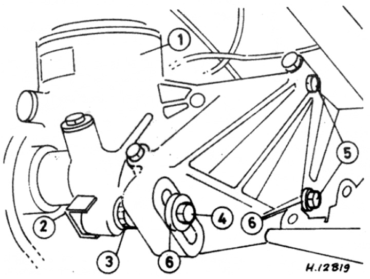
Pic. 8.24. Power steering pump mounting parts - 4-cylinder engine with multiple belts
1 Power steering pump
2 Locknut
3 Gear adjuster
4 Regulator fixing bolt
5 Mounting bolts
6 washers
25. Turn the gear adjuster bolt with an open end wrench, move the pump forward towards the motor, then remove the belt from the pulleys.
26. Fit the new belt onto the pulleys, then turn the adjusting bolt while tightening the belt so that medium finger pressure can bend it about 12mm at a point midway between the two pulleys.
27. Tighten the fixing bolt, then the two mounting bolts.
28. Install the alternator belt as described in this paragraph.
29. Check the belt tension after a few minutes of running the engine, then, where provided, install the engine protection from below.
Air conditioning compressor drive belt
30. Remove the alternator drive belt and power steering pump belt as described in this paragraph.
31. Loosen the compressor mounting bolt, unscrew the tensioner bolt to move the compressor forward to the engine and remove the belt from the pulleys (see fig. 8.31).
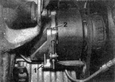
Pic. 8.31. Air conditioning compressor mounting parts - 4-cylinder engine with multiple belts
1 bolt
2 Tensioner bolt
32. Install the new belt onto the pulleys, then tighten the adjusting bolt while tightening the belt so that medium thumb force can bend it about 10mm at a point midway between the pulleys. When the tension is adjusted, tighten the mounting bolt.
33. Install the alternator and power steering pump belts as described in this paragraph.
34. Check the belt tension after a few minutes of running the engine, then, where provided, install the engine protection from below.
6-cylinder engines - replacing the drive belt
35. Remove the cooling fan blades and shroud as described in Chapter 3.
36. Loosen the tensioner bolt a quarter-half-turn (if necessary, remove the plastic plug to gain access to the bolt) (see fig. 8.36).
Pic. 8.36. Loosen tensioner bolt (1) and turn the adjusting nut (2) - 6 - cylinder engine
37. Loosen the adjusting nut (counterclock-wise) to push the adjuster back and remove the belt from the pulleys.
38. Route the new belt around the pulleys in the order shown, starting with the idler pulley (see fig. 8.38 a. b). Make sure the belt is properly seated on the pulleys.
Pic. 8.38 a. Accessory drive belt - 6-cylinder engine without air pump
Install the belt in the following order
1 tensioner pulley
2 crankshaft pulley
3 Air conditioning compressor pulley
4 Radiator fan pulley
5 Alternator pulley
6 Idler pulley
7 Power steering pump pulley
8 Water pump pulley
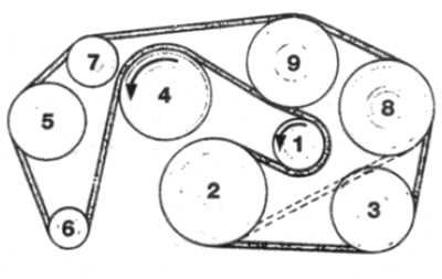
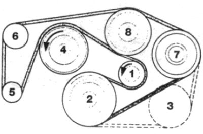
Pic. 8.38b. Accessory drive belt - 6-cylinder engine with air pump
Install the belt in the following order
1 tensioner pulley
2 crankshaft pulley
3 Air conditioning compressor pulley
4 Radiator fan pulley
5 Air pump pulley
6 Alternator pulley
7 Idler pulley
8 Power steering pump pulley
9 Water pump pulley
39. Tension the belt as follows.
Models with a graduated scale printed on the tensioner
40. Move the tensioner pointer to align with the right end of the scale (looking at the scale in front of the engine compartment) (see fig. 8.40).
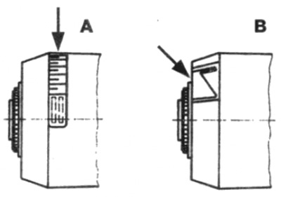
Pic. 8.40. Various types of drive belt adjusters - 6-cylinder engines
A Regulator with graduated scale
B Molded Triangle Regulator
41. On vehicles without air conditioning, turn the adjusting nut clockwise to align the tensioner pointer with the 5th scale mark.
42. On models equipped with an air conditioner, turn the adjusting nut clockwise so that the tip on the pointer is aligned with the 7th division on the scale.
43. Tighten the tensioner bolt to the required torque and install the cover (where provided).
44. Install the radiator fan blades and shroud as described in Chapter 3.
Thick Mark Models (and molded triangle) not the tensioner scale
45. Move the tensioner pointer to align with the right narrower end (looking at the dial in front of the engine bay) cabinet triangles.
46. Turn the adjusting nut clockwise until the pointer tip aligns with the thick line (on the thicker edge of the triangle) on the scale (see fig. 8.46).
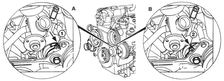
Pic. 8.46. Accessory Drive Belt Adjustment - 6 Cylinder Engine
A Tensioner indicator (1) aligned with the right edge of the arrow (marked with an arrow) on the scale - the belt is loose
B pointer tensioner (1) combined with thick pine (marked with an arrow) on the scale - the belt is tensioned
47. Tighten the tensioner bolt to the required torque and install the cover (where provided).
48. Install the radiator fan blades and shroud as described in Chapter 3.