
Models with carburetors
Note: The information in this paragraph does not apply to vehicles equipped with catalytic converters.
1. The following adjustments should be made after the engine has warmed up to normal operating temperature after a cold start, not after a long drive. All electrical appliances (including air conditioner) must be turned off and the radiator fan must not operate.
Idle speed
Note: This paragraph describes the adjustment for Stromberg type carburetors. On models equipped with Pierburg type carburetors, rpm is controlled electronically and cannot be changed manually.
2. Connect a tachometer to the engine and determine the rpm. engine. If adjustment is needed (see technical data in chapter 4A), turn the idle speed screw as far as required. Note that the xx adjustment screw is a longer screw (of two screws) (see fig. 11.2).
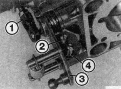
Pic. 11.2. Stromberg type carburetor adjustment screws
1 Choke lever connecting rod
2 High idle adjustment screw
3 Throttle lever
4 Idle speed adjusting screw
3. Briefly increase the engine speed, then let the engine return to idle and check the speed control xx
CO content at idle
4. Connect an exhaust gas analyzer to the exhaust pipe according to the manufacturer's instructions.
5. Increase engine speed to 2000 rpm. min. for 15 seconds, then return to idle.
6. Check the content of CO in the exhaust gases. If adjustment is needed (see technical data in chapter 4 A), remove the plug from the fuel shut-off valve, loosen the lock nut and turn the valve until the CO content meets the specification (see fig. 11.6). Recall that screwing the valve in leans the mixture, unscrewing the valve enriches the mixture. Turn the valve between measurements no more than half a turn each time.
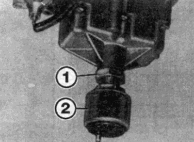
Pic. 11.6. Loosen the lock nut and turn the fuel shut-off valve until the CO content is correct
1 Locknut
2 Stop valve
Increased idle speed
Note: This paragraph describes the adjustment for Stromberg type carburetors.
7. Start the engine and let it idle. Check that the speed x.x. and the content of CO correspond to the norm.
8. Hand hold the throttle open so that the speed is 2500 rpm. min. At the same time, insert a small screwdriver into the slot on the side of the choke housing that opens when the plastic cover is removed and move the actuator lever towards the engine until you feel the restriction - do not push the lever further than this point.
9. While holding the drive lever in this position, use a screwdriver to loosen the throttle - the engine should be running at high speed xx
10. Check the overspeed xx with a tachometer. If adjustment is needed (see technical data in chapter 4A), turn the speed adjustment screw xx Note that the high idle screw is the shorter screw of the two screws (see fig. 1121
11. When finished, briefly open the throttle to disengage the xx overspeed mechanism and allow the engine to return to normal xx speed.
The content of CO in the mode of increased speed X.X.
Note: This paragraph describes the adjustment for Stromberg type carburetors.
12. Connect an exhaust gas analyzer to the exhaust pipe according to the manufacturer's instructions.
13. Set the engine to high speed xx., as described above. Check the CO content in the exhaust gases. If adjustment is needed (see technical data in chapter 4 A), remove the plug from the auxiliary air adjusting screw and turn the screw until the CO content is within the specification (see fig. 11.13). Recall that turning in the screw leans the mixture, while unscrewing the screw enriches the mixture. Turn the screw between measurements no more than half a turn each time.
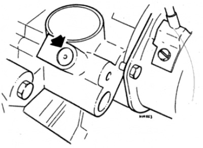
Pic. 11.13. Remove the plug (shown by arrow) from the auxiliary air adjustment screw
14. When finished, briefly open the throttle to disengage the xx overspeed mechanism and allow the engine to return to normal xx speed
Fuel injected models
Note: The following adjustments should be made after the engine has warmed up to normal operating temperature after a cold start, not after a long drive. It is best to make adjustments when the engine temperature does not exceed 100 C, or before the radiator fan turns on. On later models equipped with a rotary mechanical device for changing the idle speed, the idle speed is are electronically adjusted and adjustments are not possible without special measuring equipment Vehicles equipped with such devices must be adjusted by Mercedes workshops or Bosch fuel injection specialists.
15. When making adjustments, an air cleaner must be installed with a vacuum hose and ventilation hose connected to it. For adjustment, you can use the tachometer mounted on the instrument panel.
16. Connect an exhaust gas analyzer to the exhaust pipe, in accordance with the manufacturer's instructions.
17. Start the engine and let it run at xx speed. On models with automatic transmission, set the gear selector to "PARK" (parking). Check that all electrical consumers are turned off, including the air conditioner (where it is installed).
18. The speed adjustment screw xx can be reached through the recess on the side of the bottom of the air cleaner housing (see fig. 11.18).
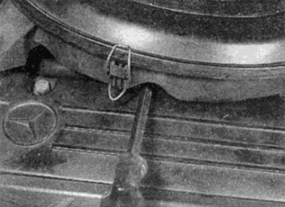
Pic. 11.18. Before the speed adjustment screw x.x. can be reached through a recess on the bottom side of the air cleaner housing
19. Turn the xx speed adjustment screw until the xx speed is within the required specification. Briefly increase engine speed and return to idle.
20. Check speed xx and adjust if necessary. Stop the engine.
21. To adjust the CO content in the exhaust gases, remove the air cleaner and pry off the plug. Install the air cleaner.
22. Start the engine and set the speed to approximately 2000 rpm. min. Maintain this RPM for approximately 10 seconds, then return to idle.
23. Use a gas analyzer to check the CO content in the exhaust gases. If it is out of specification, insert an Allen wrench into the tube of the mixture adjustment screw (see fig. 11.23). Align the end of the wrench with the adjuster and push it down against the action of the spring until the adjuster aligns with the adjuster screw.

Pic. 11.23. Insert Allen key (or long hex) into the tube of the mixture quality adjustment screw
24. Turn the adjustment screw as far as necessary to adjust the CO content; clockwise rotation enriches the mixture, and counterclockwise rotation leans it.
25. After accelerating the engine, check, as described in paragraph 8, the CO content once again, and adjust the quality of the mixture. Turn the adjustment screw only half a turn between measurements each time.
26. When finished, disconnect all gauges and install a new plug on the mixture adjustment screw tube.