



Vehicle ignition system Mercedes E-Class (W123)

Adjusting the breaker contacts
Adjustment with a set of shims 1. Remove the distributor cap. 2. Raise the rear of the vehicle with a jack, engage fourth gear and turn the engine crankshaft by rotating...
Adjustment with a set of shims 1. Remove the distributor cap. 2. Raise the rear of the vehicle with a jack, engage fourth gear and turn the engine crankshaft by rotating...

Replacing breaker contacts
1 - tip wire 2 - mounting screw Removal the moving and fixed contacts 1. Remove the ignition distributor and take out the rotor. 2. Disconnect wire tip 1 and loosen...
1 - tip wire 2 - mounting screw Removal the moving and fixed contacts 1. Remove the ignition distributor and take out the rotor. 2. Disconnect wire tip 1 and loosen...
Installing the ignition distributor
1. Install the piston of the 1st cylinder (counting from the drive side of the valve timing mechanism) to the TDC position, aligning the marks on the crankshaft pulley...
1. Install the piston of the 1st cylinder (counting from the drive side of the valve timing mechanism) to the TDC position, aligning the marks on the crankshaft pulley...
Setting the ignition timing using a stroboscope
1. Loosen the distributor housing fastening. 2. Connect the strobe light according to the operating instructions. 3. If the ignition distributor has a vacuum ignition...
1. Loosen the distributor housing fastening. 2. Connect the strobe light according to the operating instructions. 3. If the ignition distributor has a vacuum ignition...
Setting the ignition timing using a test lamp
1. Set the piston of the 1st cylinder to the TDC position, aligning the marks on the crankshaft pulley and on the timing mechanism drive cover. 2. Turn on the ignition...
1. Set the piston of the 1st cylinder to the TDC position, aligning the marks on the crankshaft pulley and on the timing mechanism drive cover. 2. Turn on the ignition...

Features of the contactless ignition system
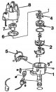
The system consists of a distributor sensor with a built-in contactless sensor, a switch and a high-energy ignition coil. Location of TSZ ignition system components 1 -...
The system consists of a distributor sensor with a built-in contactless sensor, a switch and a high-energy ignition coil. Location of TSZ ignition system components 1 -...
The operating principle of a contactless ignition system
The ignition system is contactless, of constant efficiency, and provides high voltage to the spark plugs in all engine operating modes. The system includes a distributor...
The ignition system is contactless, of constant efficiency, and provides high voltage to the spark plugs in all engine operating modes. The system includes a distributor...

Removal and installation the distributor sensor
Internal view of the ignition distributor sensor A = 3.5 cm 2 - retaining ring 3 - spacer ring Removal 1. Disconnect the wires from the battery. 2. Disconnect the...
Internal view of the ignition distributor sensor A = 3.5 cm 2 - retaining ring 3 - spacer ring Removal 1. Disconnect the wires from the battery. 2. Disconnect the...

Replacing the contactless ignition distributor sensor
Removal 1. Remove the rotor and dust shield. 2. Remove the vacuum ignition timing regulator. 3. Remove the mounting bracket 1 and carefully pull out the carrier disk in...
Removal 1. Remove the rotor and dust shield. 2. Remove the vacuum ignition timing regulator. 3. Remove the mounting bracket 1 and carefully pull out the carrier disk in...

Checking the ignition distributor sensor
1. Check the resistance of the distributor rotor. The resistance of the rotor with the interference suppression resistor should be 5000 Ohms. 2. Check that the speed...
1. Check the resistance of the distributor rotor. The resistance of the rotor with the interference suppression resistor should be 5000 Ohms. 2. Check that the speed...

Removal and installation the TDC sensor
TDC sensor (see photo in "Execution order") 1 - bracket; 2 - shoe; 3 - TDC sensor; 4 - sensor mounting bracket; 5 - contact pin; 6 - template. Template for installing...
TDC sensor (see photo in "Execution order") 1 - bracket; 2 - shoe; 3 - TDC sensor; 4 - sensor mounting bracket; 5 - contact pin; 6 - template. Template for installing...

Setting the ignition timing
1 — mark on the high voltage terminal of the spark plug of the 1st cylinder 2 — rotor of the sensor-distributor 3 — distributor sensor mounting bolt Location of the...
1 — mark on the high voltage terminal of the spark plug of the 1st cylinder 2 — rotor of the sensor-distributor 3 — distributor sensor mounting bolt Location of the...
This section is available on: russian, bulgarian, belarusian, ukrainian, serbian, croatian, romanian, polish, slovak, hungarian
More similar sections for repairing other models
☛ Power unit: Ignition system car Mercedes W168 (1997-2004)
☛ Power unit: Ignition system (I4) car Mercedes 190 (W201) (1982-1993)
☛ Power unit: Ignition and control system car Mercedes W463 (1999-2019)
☛ Power unit: Ignition and control system car Mercedes W163 (1997-2005)
☛ Power unit: Ignition and control system car Mercedes W220 (1998-2005)
Link in different formats to this section
TEXTHTMLBB Code
- General information
- Vehicle description
- Working conditions and tools
- Car care
- Diesel engines
- Engine repair
- Lubrication system
- Cooling system
- Injection system
- Supply system
- Exhaust system
- Gasoline engines
- Engine repair
- Lubrication system
- Cooling system
- Control system
- Power and exhaust system
- Transmission
- Clutch
- Mechanical gearbox
- Automatic gearbox
- Drive shafts
- Chassis
- Car suspension
- Steering
- Tires and wheels
- Brake system
- Body
- Exterior (external elements)
- Interior (internal elements)
- Doors and windows
- Heating and ventilation
- Electrical equipment
- Equipment and devices
- Power devices
- Lighting and signaling
- Electrical circuits
- General information
- Governing bodies
- Driving and operation
- Weekly care
- Maintenance (gasoline)
- Maintenance (diesel)
- Troubleshooting
- Power unit
- I4 petrol engine
- V6 petrol engine (SOHC)
- V6 petrol engine (DOHC)
- Diesel engines
- Engine overhaul
- Cooling system
- Heating and ventilation
- Fuel system (carburetor)
- Injection system «Bosch CIS-E»
- Injection system «Bosch HFM»
- Diesel fuel system
- Supply system
- Starting and charging system
- Ignition system (I4)
- Ignition system (V6)
- Preheating
- Transmission
- Clutch
- Mechanical gearbox
- Automatic gearbox
- Drive shafts
- Chassis
- Brake system
- Car suspension
- Steering
- Body
- Exterior (external elements)
- Interior (internal elements)
- Doors, locks and windows
- Electrical equipment
- Equipment and devices
- Switches
- Headlights and lighting
- Electrical circuits
- General information
- Introduction to the guide
- Power unit
- Engine device
- Repair M102 engines
- Repair M110 and M123 engines
- Cooling and lubrication (M102)
- Cooling (M110 and M123)
- Ignition system
- Power system «Stromberg»
- Power system «Solex 4A1»
- Fuel injection «K-Jetronic»
- Fuel injection «L-Jetronic»
- Transmission
- Clutch
- Mechanical gearbox
- Automatic gearbox
- Cardan and rear axle
- Chassis
- Front suspension
- Rear suspension
- Steering
- Brake system
- Body
- Exterior (external elements)
- Interior (internal elements)
- Doors, locks and windows
- Electrical equipment
- Equipment and devices
- Power devices
- Electrical circuits