
The system includes a distribution sensor with a built-in Hall generator, a switch and a special ignition coil.
Details of the sensor-distributor of the engine ignition system M 102
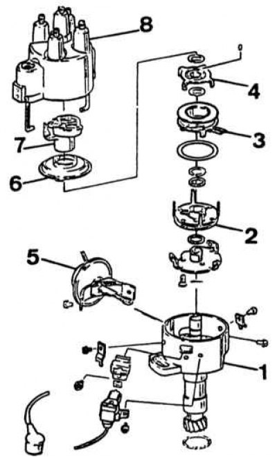
1 - body; 2 - fixed screen with teeth; 3 - induction coil; 4 - movable screen with teeth; 5 - vacuum regulator; 6 - protective screen; 7 - rotor; 8 - cover
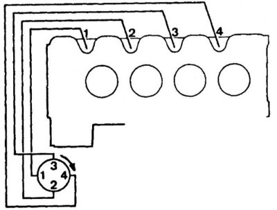
Scheme of connecting a bundle of ignition wires
The principle of operation of the Hall pulse generator
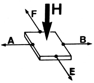
A control current flows through the semiconductor, coming from the connecting wires «A» And «IN». When the magnetic field «H» crosses a plane perpendicular to the semiconductor between the electrodes «E» And «F» there is a potential difference. This phenomenon is referred to as the Hall effect.
The Hall generator is built into the distribution sensor. It consists of fixed (magnetic barrier) and mobile (rotor) elements.
The magnetic barrier consists of a permanent magnet mounted on the screen and a Hall sensor or Hall integrated circuit placed opposite the magnet on a ceramic holder.
The rotor consists of four teeth corresponding to the number of engine cylinders. As the rotor rotates, the teeth pass through the gap between the magnet and the Hall effect sensor. When the tooth is in the gap, the magnetic field is deflected and the Hall effect is interrupted in the sensor. When it disappears, the triggering transistor becomes conductive and passes the primary current to the ignition coil. When the tooth leaves the gap, a magnetic field reappears and the passage of the primary current stops, which generates, as in a conventional ignition coil, a high voltage current going to the spark plugs.
The width of each tooth corresponds to the angle of the cam, i.e. this angle remains unchanged and does not need to be adjusted.
Like a conventional ignition distributor, the electromagnetic distributor includes centrifugal and vacuum regulators.
It is not allowed to replace the rotor of the sensor-distributor with another one with a different resistance.