
Through electrically controlled injectors, fuel is injected in pulses into the intake manifold located directly in front of the engine intake valves. The engine control unit performs sequential control of the injectors in accordance with the ignition order, regulates the injection time and thus the amount of injected fuel.
The air necessary for the formation of the fuel mixture is sucked in by the engine through the air filter and enters through the throttle valve and intake pipe to the intake valves. The amount of air intake is controlled by a throttle valve, which is moved by a stepper motor controlled by the engine control unit. For compressor engines, the intake air is compressed by a compressor driven by a V-belt. The compressed air is then cooled in the charge air cooler and enters the engine to form the fuel mixture.
The intake air volume is determined by an air quantity meter. The meter is located in the intake air duct. In the meter housing there is a thin, electrically heated sensor plate, cooled by the passing flow of intake air. The electric current heating the plate is regulated by the control system in such a way as to keep the temperature of the plate constant. If, for example, the amount of intake air increases, the temperature of the heated plate starts to decrease. At the same time, the magnitude of the electric current immediately increases in order to keep the temperature of the plate unchanged. Fluctuations in the electric current of the plate indicate to the engine control unit its load condition, which allows it to correctly determine the amount of fuel injected.
The engine control unit is located in the electronics box, on the left, near the brake fluid reservoir or directly on the engine. The control unit determines the optimal ignition timing, injection timing and the amount of injected fuel. In this case, the operation of the control unit is coordinated with other vehicle systems, for example, with the control of the gearbox or the anti-theft system.
Information from other sensors and control voltages supplied to the executive bodies ensure optimal engine operation in any situation. If some sensors fail, the control unit switches to the emergency program mode in order to exclude possible damage to the engine and ensure the further movement of the car. In this case, the engine runs unevenly and tends to stop when the gas is increased.
Sensors and executive bodies of the injection system
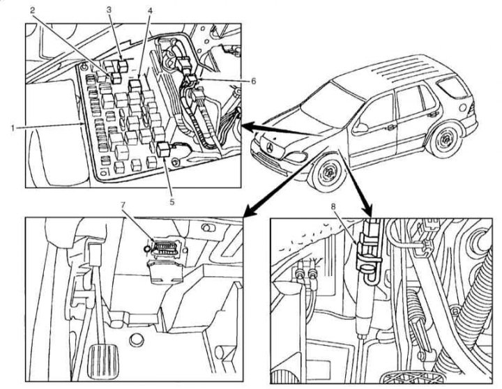
Location of components of the engine management system on the example of models 163.154/172/174
1 - Mounting block of fuses and relays; 2 - Starter relay; 3 - Fuel pump relay; 4 - Relay circuit 15; 5 - Secondary air mixing pump relay (only american models); 6 - ECM (ME-SFI); 7 - DLC diagnostic connector; 8 - Clutch pedal switch (models with manual transmission)
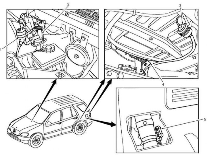
Location of components of the engine management system on the example of models 163.154/172/174
1 - Control valve for purge of the coal adsorber; 2 - Pedal position sensor; 3 - Shut-off valve of the carbon adsorber (only american models); 4 - Coal adsorber; 5 - Fuel tank pressure sensor (only american models)
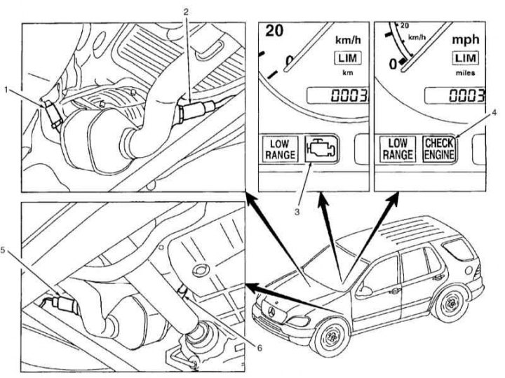
Location of components of the engine management system on the example of models 163.154/172/174
1 - Right pre-catalytic lambda probe; 2 - Right post-catalytic lambda probe; 3 - MIL warning lamp - except for American models; 4 - MIL warning lamp - American models; 5 - Left post-catalytic lambda probe; 6 - Left pre-catalytic lambda probe
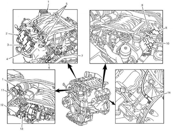
Location of components of the engine management system on the example of models 163.154
1 - Thermo-anemometric sensor for measuring air flow MAF; 2 - Ignition coil of the third cylinder; 3 - Ignition coil of the second cylinder; 4 - Ignition coil of the first cylinder; 5 - Fuel injectors; 6 - Camshaft Hall sensor; 7 - Coolant temperature sensor (ECT); 8 - Ignition coil of the sixth cylinder; 9 - Ignition coil of the fifth cylinder; 10 - The ignition coil of the fourth cylinder; 11 - Air pump relay (only american models); 12 - Air pump switch valve (only american models); 13 - Pressure sensor (only american models); 14 - Crankshaft position sensor (CKP)
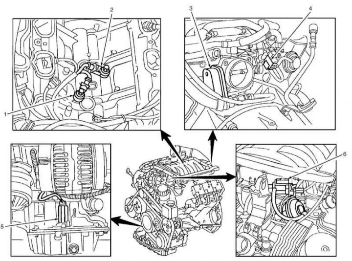
Location of components of the engine management system on the example of models 163.154
1 - Right knock sensor (KS 1); 2 - Left knock sensor (KS 2); 3 - Actuator EA/CC/ISC; 4 - EGR vacuum transducer; 5 - Oil level/quality sensor; 6 - Resonance valve-switch of the inlet pipeline
The location of the individual elements of the engine management system is shown in the illustrations on the example of individual models.
crankshaft position sensor (CKP) screwed into the cylinder block at the flywheel. It transmits to the control unit information about the engine speed and the TDC position of the piston of the first cylinder.
Camshaft position sensor (CMP) located at the end of the cylinder head cover. Together with the crankshaft position sensor, it transmits to the control unit information about the TDC of the piston of the first cylinder. It serves to synchronize the ignition timing and ignition sequence.
Throttle actuator consists of an electric motor and two potentiometers. The mechanism regulates the position of the throttle valve, ensuring the stability of the idle speed, regardless of the connection of additional consumers of energy, such as a power steering or an A/C compressor.
Throttle position sensor (TPS) mounted in the throttle actuator and outputs to the control unit (ECM) information about the current throttle angle. The second potentiometer provides the ECM with a base value and provides a backup signal if the throttle potentiometer fails.
Gas pedal position sensor located in the area where the driver's feet are located directly on the axis of the gas pedal. It informs the control unit about the position of the pedal. For safety reasons, an additional signal is taken from the pedal sensor, in the same way as from the throttle potentiometer.
coolant temperature sensor (ECT) located in the thermostat housing. It is a negative temperature coefficient resistor (NTC), whose resistance decreases with increasing temperature.
intake air temperature sensor (IAT) is also an NTC resistor.
Fuel Tank Ventilation/Fuel Evaporation System (EVAP) consists of a carbon adsorber and an electromagnetic valve for controlling the purge of the latter. The adsorber accumulates fuel vapors formed as a result of its heating. When the engine is running, fuel vapor accumulated in the adsorber is drawn into the intake tract and sent to the combustion chambers.
lambda probes (oxygen sensors) they measure the oxygen content in the exhaust gases before and after the catalytic converter and transmit the corresponding signals to the engine control unit. One lambda probe is located before and the other after the catalytic converter.
Sensor (And) detonation (KS) is screwed directly into the body of the cylinder block and serves to prevent the occurrence of dangerous impact combustion of the fuel mixture, allowing you to keep the ignition timing at the knock limit, when the efficiency of the engine output is maintained at a maximum level with a minimum fuel consumption.