
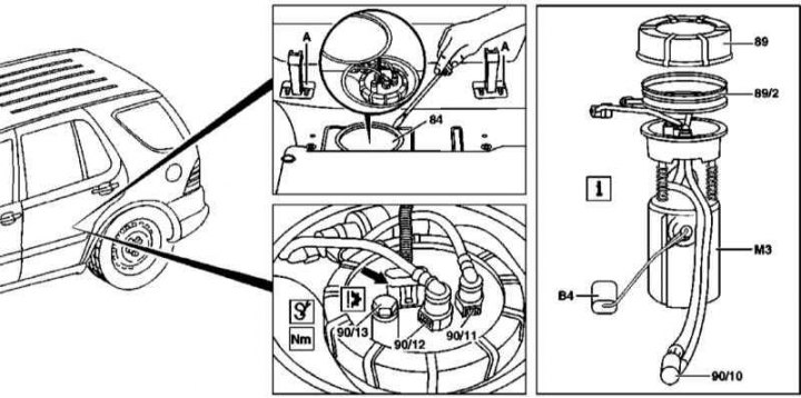
Installation Details of Fuel Pump Assembly with Fuel Gauge (all models)
A - Rear seat frame brackets
Arrow — Contact socket of electroconducting of the fuel pump
1. Details of the installation of the fuel pump assembly are shown in the illustration, to which all references in the text refer.
2. Empty the fuel tank (see Section Emptying the fuel tank).
3. By following the procedures in paragraphs 2 to 6 of Section Emptying the fuel tank, remove the cover (84) access windows to the fuel pump/fuel gauge assembly.
4. Disconnect the connector (arrow) fuel pump wiring.
5. Disconnect supply lines from pump assembly (90/12) and return (90/11) fuel, if equipped, also disconnect the fuel line of the stationary heater (90/13), - try not to kink the fuel lines.
Note. If a stationary heater is not installed, do not attempt to remove the connection screw.
6. Using a suitable wrench, loosen the ring nut (89).
Note. The ring nut must be replaced without fail.
7. Carefully remove the fuel pump/fuel gauge assembly (M3/B4) from the gas tank, - try not to bend the sensor float lever.
Attention! The pump with the sensor is combined into a single unit that cannot be disassembled!
8. Installation is carried out in the reverse order - lubricate the sealing element (89/2) oil.