
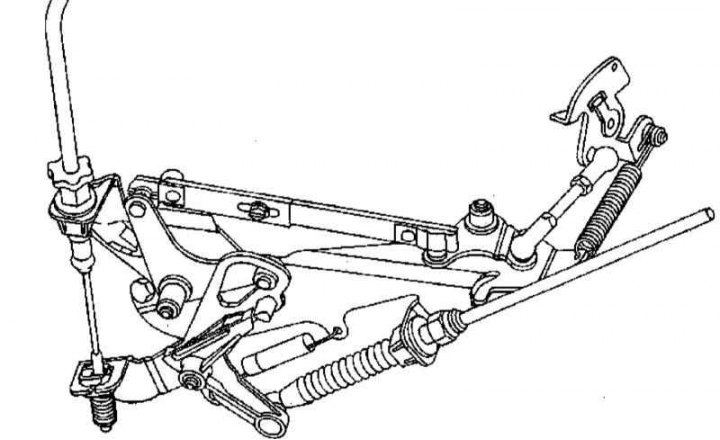
Throttle lever design
Throttle lever design
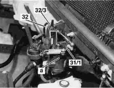
31/1 - Transfer lever; 32 - Drive cable; 32/3 - Adjusting screw; a - Idling limiter
Throttle lever design
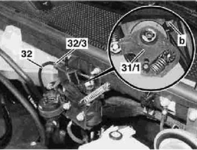
31/1 - Transfer lever; 32 - Drive cable; 32/3 - Adjusting screw; b - Throttle limiter
1. The design of the throttle lever drive is shown in the illustrations, if necessary, dismantle the air cleaner (see Section Removal and installation of components of an inlet air path).
2. Lubricate the pivot joints of the drive mechanism.
3. Slowly squeeze all the way, then release the gas pedal - if there are signs of play or jamming, replace the throttle cable (see below).
Checking and adjusting the throttle actuator
Models 163.136

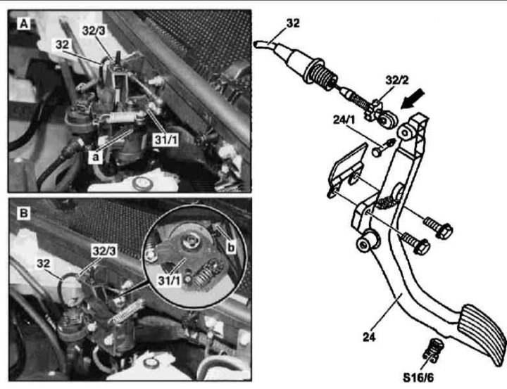
Throttle actuator adjustment on models 163.136 (111 series engine)
2 - Base plate of the throttle actuator regulator; 24 - Gas pedal; 30/4 - Plastic retainer; 30/5 - Guide element; 32 - Throttle actuator cable; 32/2 - Adjusting nut; 32/3 - Adjusting screw; 32/4 - Connecting rod; 32/5 - Throttle actuator lever; 32/6 - Support arm; 32/7 - Control lever; 32/8 - Roller; 32/9 - Torsion spring; 38 - Maximum throttle opening limiter; Arrow - Full throttle activator stop
Illustrative material for checking and adjusting the throttle actuator on models 163.136 (111 series engine) presented in the illustration, which includes all references in the text.
Examination
1. Turn off the ignition.
2. Release the cover on the base plate (2) throttle actuator controller.
3. Check the smooth running of the connecting rod (32/4) gas cable (32), replace obviously faulty components (see below).
Adjustment
With closed throttle
1. Release the connecting rod (32/4) on the throttle control lever (32/5) and assess the condition of the idle speed limiter.
2. Expand the lever (32/5) clockwise until it stops at the idle speed limiter.
3. Rotate the spherical seat to freely adjust the position of the connecting rod (32/4) on throttle control lever support (32/5).
4. Plant the stem (32/4) into the spherical support of the lever (32/5) and secure it with a locknut.
5. Fully release the gas pedal (24), - video clip (32/8) support arm (32/6) should rest freely against the idle speed limiter.
At wide open throttle
1. Turn to the left, release the maximum throttle opening limiter (38).
2. Squeezing the gas pedal (24), open the throttle just enough so that the drive lever (32/5) hit the activator (arrow).
3. Turning to the right, fix the stop (38) in the adjusted position.
Evaluation of adjustment results
Check for full throttle travel.
Disassembly and assembly of the throttle actuator regulator
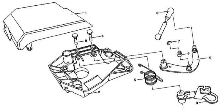
The design of the throttle actuator regulator on models 163.136 (111 series engine)
1 - Cover; 2 - Base plate; 3 - Support arm; 4 - Control lever; 5 - Torsion spring; 6 - Roller; 7 - Lock washer; 8 - Screws; 9 - Connecting rod
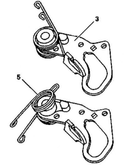
The design of the spring assembly of the throttle actuator regulator on models 163.136 (111 series engine)
3 - Support arm
5 - Torsion spring
1. The design of the throttle actuator regulator used on models 163.136 (111 series engine) shown in the illustrations, which include all references in the text.
2. During disassembly, try to memorize the mounting positions of the components to be removed as much as possible, paying special attention to the torsion spring (5) and lever roller (6). Replace defective parts.
3. When installing axial screws (8) during assembly, make sure that both levers are (4 and 3) axial play within 0.1÷0.3 mm.
4. After completing the assembly, make sure that the regulator functions properly
Models 163.154/157/172/174/175
Throttle actuator adjustment on models 163.154/157172/174/175 (112 and 113 series engines)
A - Idling; B - Full throttle; a - Idling limiter; b - Throttle limiter
Illustrative material for checking and adjusting the throttle actuator on models 163.154/157172/174/175 (112 and 113 series engines) presented in the illustration, which includes all references in the text.
Examination
Check the smoothness and condition of the shift lever position sensor (31/1) and drive cable (32). Replace defective components.
Adjustment
1. Depress the gas pedal (24) all the way to the kickdown switch (S16/6), but without activating the latter.
2. Turning the adjusting screw (32/3) make sure that the lever position sensor (31/1) hit the throttle limiter (b).
3. When the gas pedal is released, the sensor should rest against the idle speed limiter (A), - achieve this requirement by turning the adjusting nut (32/2), - alternatively, you can use the same nut to completely select the free play of the pedal.
4. Make sure that the throttle valve travels fully.
Removal and installation of the throttle cable Model 163.136
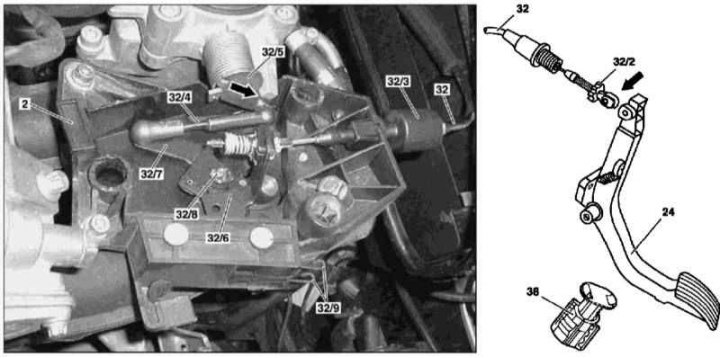
Throttle actuator adjustment on models 163.136 (111 series engine)
2 - Base plate of the throttle actuator regulator; 24 - Gas pedal; 30/4 - Plastic retainer; 30/5 - Guide element; 32 - Throttle actuator cable; 32/2 - Adjusting nut; 32/3 - Adjusting screw; 32/4 - Connecting rod; 32/5 - Throttle actuator lever; 32/6 - Support arm; 32/7 - Control lever; 32/8 - Roller; 32/9 - Torsion spring; 38 - Maximum throttle opening limiter; Arrow - Full throttle activator stop
1. Details of the installation of the throttle cable on models 163.136 (111 series engine) shown in the illustration, which includes all references in the text.
2. Remove the throttle actuator regulator cover.
3. Move the support arm by hand (32/6) to the position corresponding to the full opening of the throttle valve (arrow) and while holding it, release the drive cable (32) from the guide (32/6).
4. Detach the guide element (32/5) from support arm (32/6) and remove the last assembly with the drive cable (32).
5. Squeeze the plastic retainer (30/4) and release it from the base plate (2) complete with drive cable (32).
6. Disconnect the end of the cable (arrow) from the gas pedal (24).
7. Push the cable from the passenger compartment into the engine compartment - make sure that the bushing remains in place in the bulkhead.
8. Remove the cable assembly from the engine compartment.
9. Installation is carried out in the reverse order, - an open section of the cable between the guide element (30/5) lubricate with an anti-corrosion compound, make sure that the fixing pin fits securely (24/1).
10. Finally, check that the cable is correctly adjusted and, if necessary, make the necessary adjustments.
Models 163.154/157/172/174/175
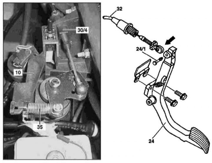
Details of the throttle cable installation on models 163.154/157172/174/175 (112 and 113 series engines)
35 - Return spring
Arrow - Rope end
1. Details of the installation of the throttle cable on models 163.154/157172/174/175 (112 and 113 series engines) shown in the illustration, which includes all references in the text.
2. Disconnect the drive cable (32) from the ball head.
3. Squeeze the plastic retainer (30/4) and detach it from the fixed lever (10) complete with drive cable (32).
4. Remove the cover installed on the left under the instrument panel.
5. Disconnect the end of the cable (arrow) from the gas pedal (24).
6. Push the cable from the passenger compartment into the engine compartment - make sure that the bushing remains in place in the bulkhead.
7. Remove the cable assembly from the engine compartment.
8. Installation is carried out in the reverse order - make sure that the mounting pin is firmly seated (24/1).
9. Finally, check the correct adjustment of the cable, if necessary, make the necessary adjustments.
Removal and installation of the activator of the device of stabilization of idling (ISC), - models 163.136
Details of the throttle cable installation on models 163.136 (111 series engine)
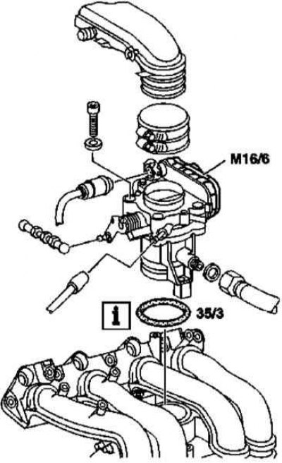
35/3 - O-ring
М16/6 - ISC Activator
1. Installation details of the ISC activator on models 163.136 (111 series engine) shown in the illustration, which includes all references in the text.
2. Remove the air cleaner bypass sleeve (see Section Removal and installation of components of an inlet air path).
3. Remove the crankcase ventilation hose.
4. Loosen the fixing screw and remove the ISC activator.
5. Installation is in reverse order - do not forget to replace the sealing ring (35/3), check that the ventilation hose is connected correctly.
Removal and installation of the electronic accelerator actuator, - models 163.154/157/172/174
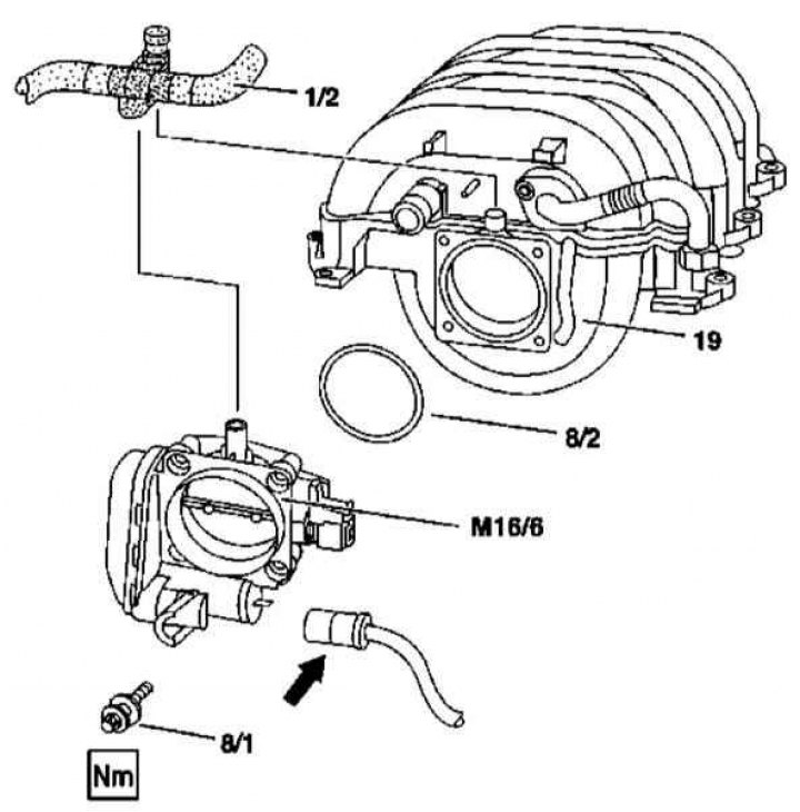
Installation details of the electronic accelerator actuator on models 163.154/157/172/174 (112 and 113 series engines)
1. Installation details of the electronic accelerator actuator on models 163.154/157/172/174 (112 and 113 series engines) shown in the illustration, which includes all references in the text.
2. Remove the cylinder head cover trim panel/air cleaner.
3. Remove the air duct with the built-in MAF sensor (see Section Removal and installation of components of an inlet air path).
4. Disconnect the vent line (1/2) from intake manifold (19).
5. Disconnect the electrical wiring connector (arrow)
6. Turn out bolts (8/1) and remove the actuator (М16/6).
7. Installation is in reverse order - do not forget to replace the sealing ring (8/2), check the reliability of fixing the contact connector (arrow).
Removing and installing the gas pedal
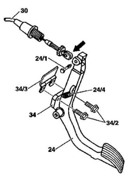
Accelerator pedal installation details (all models)
24 - Gas pedal; 24/1 - Pin; 24/4 - Return spring; 30 - Throttle actuator cable; 34 - Axial bracket; 34/2 - Mounting bolts; 34/3 - Blocking plate
1. Details of the installation of the gas pedal are shown in the illustration, which includes all references in the text.
2. When assembling, make sure the pin fits securely (24/1).