
Lubrication, checking the mobility and condition of the swivel joints of the throttle linkage
Attention! Try not to get grease on the plastic hinges of the drive!
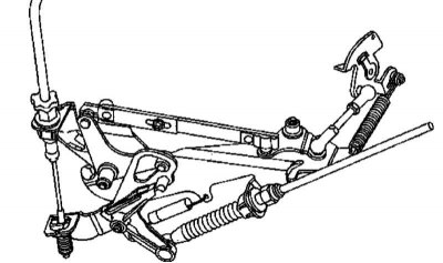
Throttle lever design | 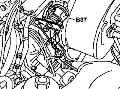
Location of the gas pedal position sensor (B37) |
1. The design of the throttle lever drive is shown in the illustrations above, if necessary, dismantle the air cleaner (see Section Removal and installation of components of an inlet air path).
2. Lubricate the pivot joints of the drive mechanism, the ball assemblies should be separated, filled with grease, then re-joined - do not forget the spherical support on the gas pedal position sensor (B37).
3. Thoroughly lubricate all bearing surfaces of rods and levers, as well as exposed areas of hinges and cables.
4. Slowly squeeze all the way, then release the gas pedal - if there are signs of play or jamming, replace the throttle cable (see below).
Checking and adjusting the throttle actuator
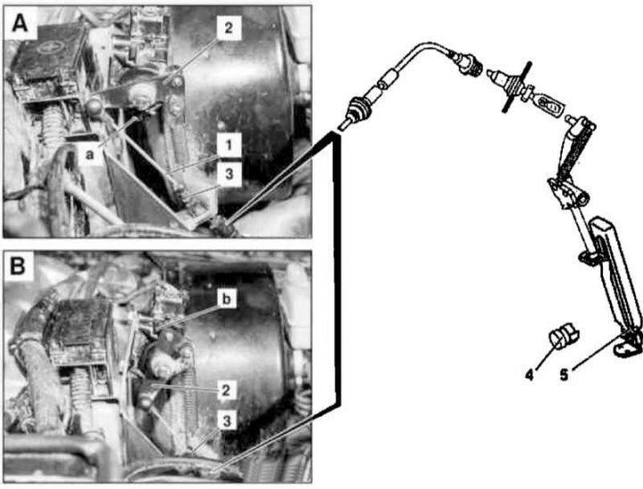
1 - Drive cable; 2 - Position sensor lever; 3 - Adjusting screw; 4 - Sensor-switch for activation of the kickdown mode; 5 - Gas pedal; A - The damper is completely closed; a - damper stop; B - The damper is completely closed; b - damper stop
1. Check the freedom of movement and the general condition of the lever (2) position sensor (TPS) and drive cable (1).
2. Start the engine at idle, - the lever (2) TPS should be pressed against the stop (A) damper closed position (gas pedal (5) released). If necessary, correct the position of the lever by turning the adjusting screw (3), fully selecting the existing backlash.
3. Connect the STAR DIAGNOSIS reader and clear the memory of the OBD module (see chapter Engine Electrical Systems).
4. Depress the gas pedal (5) all the way into the sensor-switch for activating the kickdown mode (4) (do not activate the mode), and using the adjusting screw (3) make sure that the TPS lever is pressed against the stop (b).
5. Clear the memory of the OBD module again (see chapter Engine Electrical Systems).
6. Visually inspect the full throttle travel, lubricate the exposed sections of the drive cable with anti-corrosion grease (001 989 37 51 10).
Removing and installing throttle cable
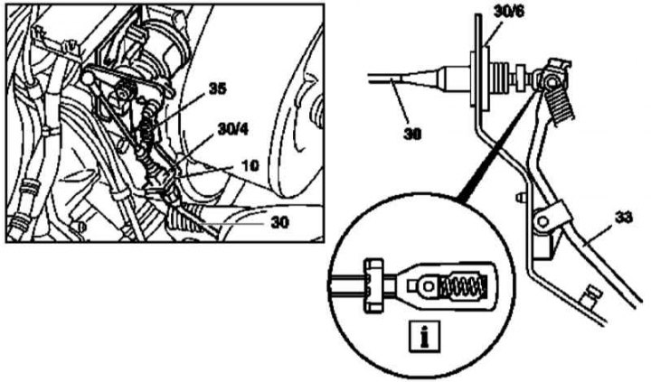
Throttle cable installation details (all models)
10 - Fixed lever; 30 - Drive cable; 30/4 - Plastic clips; 30/6 - Rubber bushing; 33 - Pedal assembly lever; 35 - Return spring
1. Disconnect the drive cable (30) from the head of the spherical bearing.
2. Squeeze the plastic tabs together (30/4) and pull out the fixed lever (10) complete with drive cable (30).
3. Remove the cover on the left under the instrument panel.
4. Push the cable from the passenger compartment into the engine compartment - try not to let the rubber bushing fall out (30/6).
5. Remove the cable assembly (30) from the engine compartment.
6. Installation is carried out in the reverse order.
7. Finally adjust the drive (see above) and lubricate the exposed areas of the cable assembly with anti-corrosion grease (001 989 37 51 10).
Removal and installation of the gas pedal position sensor
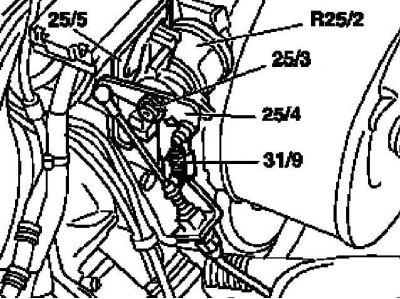
Installation details of the gas pedal travel sensor (all models)
25/3 - Lock washer; 25/4 - Transmission lever with built-in remote clutch; 25/5 - Fixed lever; 31/9 - Return spring; R25/2 - Setpoint sensor
1. Disconnect the return spring (31/9).
2. Caulk out the lock washer (25/3).
3. Pull back the transmission arm with built-in distance clutch (25/4), - do not disconnect the throttle cable
4. Disconnect the electrical connector.
5. Unbolt the gas pedal position sensor (R25/2) from a fixed lever (25/5).
6. Installation is carried out in the reverse order - make sure that the lock washer is seated correctly. Check the correct operation of the drive, if necessary, make the appropriate adjustment (see above).
Removing and installing the gas pedal and its lever
Pedal
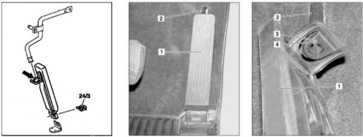
Accelerator pedal installation details (all models)
1 - Gas pedal; 2 - Pedal rod; 3 - Sample; 4 - Cam; 24/3 - Retainer
1. Remove the latch (24/3).
2. Disconnect the lower end of the gas pedal (1).
3. Turn the pedal (1) to the left on the stem (2) so that the sample (3) got on the fist (4) stock (2).
4. Remove the pedal by pushing it back and separating it from the stem.
5. Installation is carried out in the reverse order.
Pedal lever
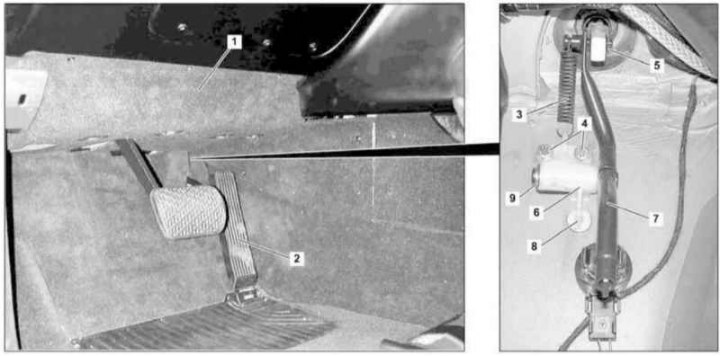
Details of installation of the lever of a pedal of gas (all models)
1 - Cover; 2 - Gas pedal; 3 - Spring; 4 - Bolts; 5, 9 - Retaining rings; 6 - Rotary support; 7 - Pedal lever; 8 - Locking pin
1. Remove the cover (1) on the left under the instrument panel.
2. Remove the pedal assembly (2) (see above).
3. Remove the front section of carpet in the driver's footwell.
4. Remove the spring (3).
5. Turn out bolts (4) swivel brackets (6) to the bulkhead of the engine compartment.
6. Remove retaining ring (5).
7. Remove the swivel support (6) complete with pedal lever (7).
8. Remove locking pin (8) and separate the support (6) from the lever (7).
9. Installation is carried out in the reverse order - make sure that the pin (8) hit the receiving nest in the bulkhead of the engine compartment.