
Air cleaner and air filter
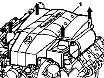
Removing the cover of the power unit with an integrated air cleaner | 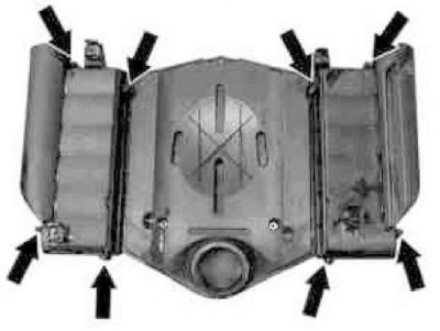
Air cleaner element installation details |
1. Pull up to remove the power unit cover with built-in air cleaner (1).
2. Remove the filter element from under the cover and replace it with a replacement one.
3. Replace the cover (1).
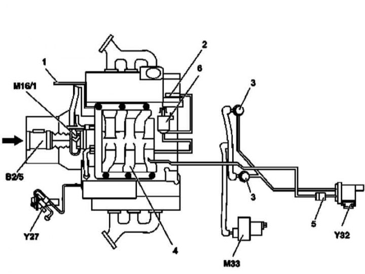
Air intake assembly with air mass sensor (MAF)
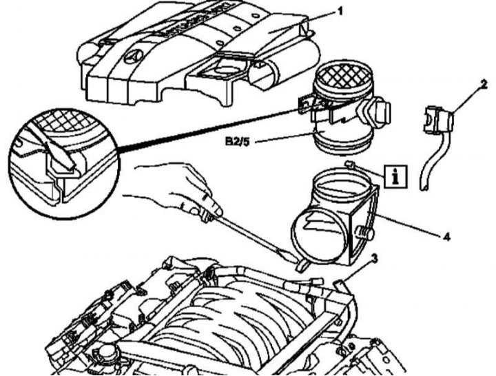
Air intake assembly installation details with MAF sensor
1 - Power unit cover with built-in air cleaner
2 - MAF sensor wiring connector
3 - Crankcase ventilation line
4 - Air intake
B2 / 5 - MAF sensor
1. Remove the cover of the power unit with built-in air cleaner (1).
2. Disconnect the wiring (2) from MAF sensor (B2/5).
3. Disconnect the crankcase ventilation line (3).
4. Release the crankcase ventilation line to the right of the MAF sensor (B2/5).
5. Using a screwdriver, release the MAF sensor mounting clip (B2/5).
6. Press down the latch on the electronic throttle actuator and remove the air intake (4) complete with MAF sensor (B2/5).
7. Disconnect the sensor assembly (B2/5) from the air intake (4).
8. Installation is carried out in the reverse order.
Inlet pipeline
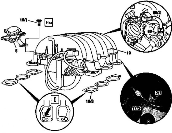
Details of installation of the inlet pipeline
6 - Combined valve; 19 - Inlet pipeline; 19/1 - Bolts; 19/3 - Sealing gaskets; 89 - EGR valve; 89/2 - EGR line; Arrow - Combination valve hole
Inlet piping connection diagram
1 - Secondary vacuum; 2 - Vacuum block of the control damper; 3 - Air injector of the combined valve; 4 - Inlet pipeline; 5 - Control valve; 6 - Control damper of the valve-switch; В2/5 - MAF sensor; M16 / 1 - Electronic throttle actuator; M33 - Electric air pump; Y27 - EGR switch valve; Y32 - Air pump switch valve
1. Remove air intake assembly with MAF sensor (see above).
2. Remove the fuel distribution line with injectors (see Section Removal and installation of the fuel distributive highway and injectors).
3. Disconnect the relevant electrical wiring.
4. Loosen the union nut of the ventilation line (89/2) to the EGR valve (89), - to prevent the fitting from turning, hold it with a second wrench.
5. Turn out fixing bolts (19/1) and remove the combination valve (6).
6. Remove the intake manifold assembly (19), - Seal the engine intake ports immediately with a lint-free cloth.
7. Remove gaskets (19/3), - gaskets must be replaced without fail.
8. Installation is carried out in the reverse order. New gaskets are first fixed with studs (check the correct position of the gaskets), which are then turned out just before the installation of the pipeline.
Electronic throttle actuator
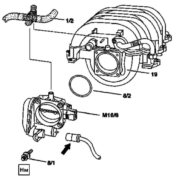
Installation details of the electronic throttle actuator
1/2 - Crankcase ventilation line; 8/1 - Bolts; 8/2 - O-ring; 19 - Inlet pipeline; M16 / 6 - Electronic throttle actuator; Arrow - Connector
1. Remove the cover of the power unit with the air cleaner built into it (see above).
2. Remove air intake assembly with MAF sensor (see above).
3. Disconnect from the inlet pipeline (19) crankcase ventilation line (1/2).
4. Disconnect the wiring (arrow).
5. Turn out fixing bolts (8/1) and remove the throttle actuator (М16/1), - prepare a replacement sealing ring (8/2).
6. Installation is carried out in the reverse order.
Resonator chamber with water collector
Details of the installation of the resonator chamber of the intake air path and the water collector (all models) (1 of 2)
1 - Bolts; 2 - Mounting clamp; 3 - Drainage hose; 9 - Resonator chamber with water collector
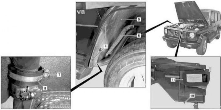
Details of the installation of the resonator chamber of the intake air path and the water collector (all models) (2 of 2)
4 - Screws; 5 - Locker; 6 - Thermal protection screen; 7 - Nut; 8 - Mounting clamp; 10 - Bolt; 11 - Sealing gasket
1. Open the hood.
2. Turn out three fixing bolts (1).
3. Release the clamp (2) and remove the drain hose (3), - in order to provide access, remove the locker (5) wheel arch protection (see chapter Body).
4. Give the nut (7) and remove the clamp (8).
5. Remove the resonator chamber assembly with water trap (9), - make sure that the drain hose is pointing upwards.
6. Check the condition of the gasket (11), replace if necessary.
7. Installation is carried out in the reverse order. Before screwing in the bolt (10) should be lightly lubricated - make sure that the bolt fits correctly in the guide.