
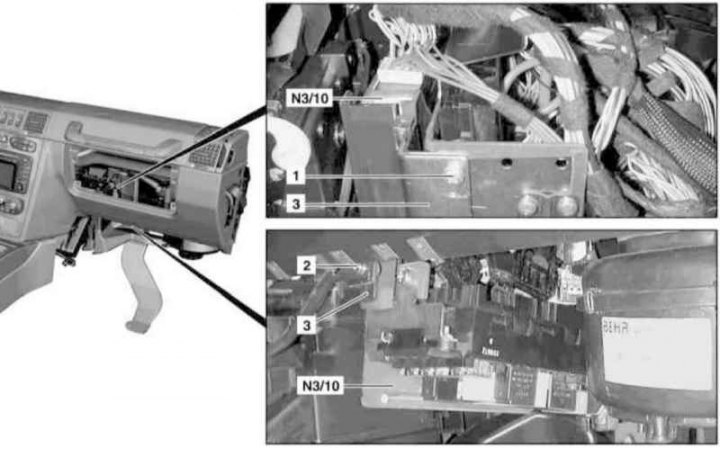
Installation Details of the Fuel Injection Control Module (1 of 2)
1, 2 - Bolt
3 - Module support bracket
N3/10 — (ECM ME-SFI)
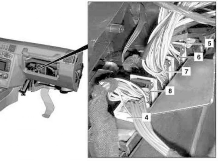
Installation Details of the Fuel Injection Control Module (2 of 2)
4, 5, 6, 7 - Connectors
1. On models of the corresponding configuration (code ET2) activate the service mode of the TELE AID emergency call system (see Section Activation / deactivation of the service mode of the TELE AID emergency call system).
2. Disconnect the negative cable from the battery.
3. Turn on the auxiliary battery and connect it to the standard battery, then disconnect the negative cable from the latter.
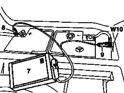
7 - Auxiliary battery
8 - Module positive wire terminal
9 - Terminal of the negative wire of the module
W10 - Battery Ground
4. Remove the front carpet panel in the passenger footwell.
5. Remove the signal activation and sensing module assembly (SAM) with front fuse/relay mounting block (see chapter Onboard electrical equipment), - do not disconnect the wiring.
6. Turn out bolts (1 and 2) and remove the support bracket (3) ECM.
7. Disconnect the wiring connectors (4, 5, 6, 7 and 8), - do not forget to release the latches where they are provided.
8. Remove ECM ME-SFI (N3/10).
9. Installation is carried out in the reverse order - follow the correct laying and connection of the electrical wiring.
10. In conclusion (with appropriate equipment) deactivate the service mode of the TELE AID system (see Section Activation / deactivation of the service mode of the TELE AID emergency call system) and clear the memory of the processor of the on-board self-diagnosis system (see chapter Engine Electrical Systems).