
Air intake installation details on models 163.136 (111 series engine)
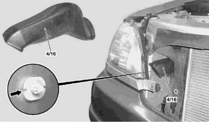
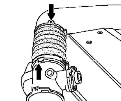
4/16 - Air intake
Arrow - Retainer
Air intake installation details on models 163.136 (111 series engine) shown in the illustration, - first remove the radiator grille (see chapter Body).
Air cleaner
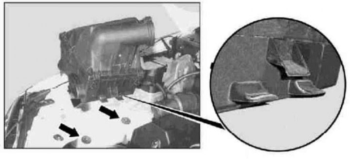
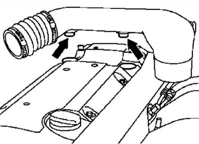
Air cleaner installation details on models 163.136 (111 series engine)
Arrows - Rubber pads
Air cleaner installation details on models 163.136 (111 series engine) shown in the illustration - do not forget to release the coolant hose from the guide on the air cleaner housing.
Air mass sensor (MAF)
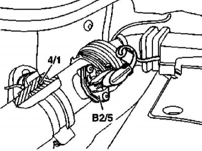
MAF sensor installation details on models 163.136 (111 series engine)
B2 / 5 - MAF sensor
MAF sensor installation details on models 163.136 (111 series engine) shown in the illustration - do not forget to replace the O-ring.
Air cleaner bypass sleeve
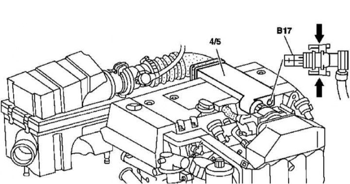
Details of installation of a bypass air sleeve on models 163.136
4/5 - Air cleaner bypass sleeve
B17 - Air temperature sensor supplied to the passenger compartment
Arrows - Fasteners
Details of installation of a bypass air sleeve on models 163.136
Arrows - Fasteners
Details of installation of a bypass air sleeve on models 163.136
Arrows - Fasteners
Details of installation of a bypass sleeve of an air cleaner on models 163.136 (111 series engine) shown in the illustrations.
Models 163.154/157
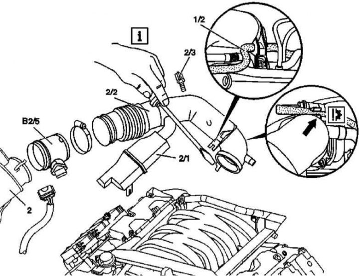
Details of installation of components of an inlet air path on models 163.154/157 (112 series engines)
1/2 - Right crankcase ventilation line; 2 - Air cleaner; 2/1 - Resonator chamber; 2/2 - Air duct; 2/3 - Bolt; B2/45 - MAF sensor
Details of installation of components of an inlet air path on models 163.154/157 (112 series engines) shown in the illustration. Before removing the air sleeve (2/2) Disconnect the electronic accelerator cable (arrow), - use a screwdriver to press down the locking tab of the air sleeve fixing latch (2/2) to the actuator of the electronic accelerator.
Models 163.172/174/175
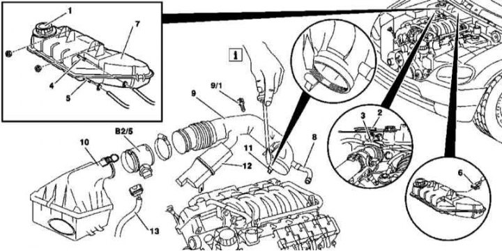
Details of installation of components of an inlet air path on models 163.172/174/175 (113 series engines)
1 - Cover of the expansion tank of the cooling system; 2 - Overflow tube; 3 - Line of the cooling path; 4 - Line of the cooling path; 5 - Line of the cooling path; 6 - Pin connector; 7 - Expansion tank; 8 - Vacuum hose of the crankcase ventilation system; 9 - Air duct; 9/1 - Bolt; 10 - Air cleaner; 11 - Air duct clamp; 12 - Resonator chamber; 13 - Pin connector of the electrical wiring of the MAF sensor; В2/5 - MAF sensor
1. Details of installation of components of an inlet air path on models 163.172/174/175 (113 series engines) shown in the illustration, which includes all references in the text.
2. Opening the lid (1), relieve excess pressure in the expansion tank of the cooling system (7).
3. Disconnect from expansion bottle (7) overflow tube (2).
4. Disconnect from expansion bottle (7) lines (3, 4 and 5) cooling path.
5. Remove expansion tank (7).
6. Disconnect the connector (6) MAF sensor (B2/5).
7. Disconnect the vacuum hose (8) crankcase ventilation systems.
8. Removing the bolt (9/1), separate the air sleeve (9) from the cylinder head cover.
9. Remove from air cleaner (10) MAF sensor (B2/5).
10. Press the locking mechanism down with a screwdriver (11) air sleeve.
11. Remove the resonator chamber (12).
12. Take off the sleeve (9) complete with MAF sensor (B2/5).
13. Installation is carried out in the reverse order.