
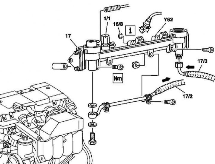
Details of installation of the fuel line on models 163.136 (111 series engine)
1/1 - Service valve; 16/8 - O-ring; 17 - Fuel line; 17/2 - Fuel return line; 17/3 - Fuel supply line; Y62 - Injector
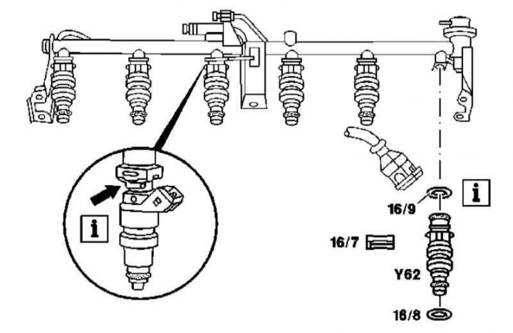
Details of installation of fuel injectors on models 163.136 (111 series engine)
16/7 - Anti-rotation lock
Arrow - 4-point nozzle
1. Details of the installation of the fuel distribution line and injectors on models 163.136 (111 series engine) shown in illustration and illustration Service valve location (1/1) pressure relief on the fuel line of the 111 series engine. Service valve location (1/1) pressure relief on the fuel line of the 111 series engine, which include all references in the text.
2. Remove the air cleaner bypass sleeve (see Section Removal and installation of components of an inlet air path).
3. Depressurize the supply system through the service valve (see Section Relieving pressure in the fuel system of a gasoline engine).
4. Turn out fixing bolts and remove a fuel highway (17).
5. Disconnect return lines (17/2) and filing (17/3) fuel and injector wiring (Y62)
6. If necessary, remove the fuel injectors (Y62).
7. Install in reverse order - do not forget to replace the O-rings (16/8 and 16/9), which must be lubricated with oil before installation.
Models 163.154/157/172/174
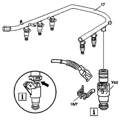
Details of installation of fuel injectors on models 163.154/157/172/174 (111 series engine)
16/7 - Anti-rotation lock
Arrow - 4-point nozzle
1. Details of installation of the fuel distribution line and injectors on models 163.154/157/172/174 (112 and 113 series engines) shown in illustration and illustration Service valve location (1/1) pressure relief on the fuel line of engines series 112 and 113, which includes all references in the text.
2. Remove the cylinder head cover trim panel/air cleaner.
Note. On models with an air cleaner mounted on the engine, remove the resonator chamber (2/1).
3. Remove the screws (1/4) and remove the plastic cover.
4. Depressurize the supply system through the service valve (see Section Relieving pressure in the fuel system of a gasoline engine).
5. Disconnect the fuel supply line (17/2).
6. Disconnect the electrical wiring from the injectors (Y62).
7. Remove the fixing screws (17/1) and remove the fuel line assembly (17) with injectors (Y62) from the intake pipe.
8. If necessary, remove the injectors.
9. Install in reverse order - do not forget to replace the O-rings (16/8 and 16/9), which must be lubricated with oil before installation.