
General information
The composition of the fuel system includes: installed at the rear of the car (under the rear seat cushion) fuel tank with activated charcoal adsorber, fuel lines, electric fuel pump, and electronic sequential injection system controlled by the control unit.
The fuel reserve is shown to the driver on the instrument panel. In a gasoline engine, gasoline vapors are collected in an adsorber and fed into the combustion chambers of the engine.
Driving style has a significant impact on fuel consumption. Below are a few tips for sensible use of the gas pedal.
- After starting the engine, immediately move off, even if this happens in the cold;
- When the car stops for more than 40 seconds, turn off the engine;
- Always drive in the highest possible gear;
- When driving long distances, maintain a steady speed whenever possible. Avoid driving at high speeds. Drive carefully. Do not slow down unnecessarily;
- Do not transport excess cargo on the vehicle. If the roof rack is not in use, remove it from the roof;
- Check tire pressure. Avoid excessive pressure reduction.
Functional diagrams of injection systems, diagrams of vacuum connections and the location of components of engine management systems
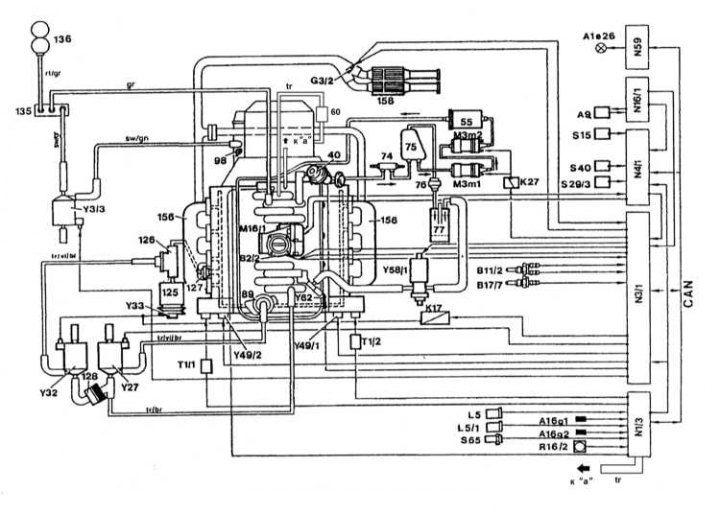
Functional diagram of the injection system of engines 119 and 104 (engine shown 119)
40 - Diaphragm pressure regulator; 55 - Fuel filter; 60 - Vacuum device; 74 - Fuel cooler; 75 - Fuel tank; 76 - Ventilation valve; 77 - Carbon adsorber for gasoline vapors; 89 - EGR valve (left on engine 120); 89a - Right EGR valve on the 120 engine; 98 - Damper pneumatic upshift device; 125 - Air pump; 126 - Shut-off valve for mixing air into the exhaust manifold; 127 - Check valve for mixing air into the exhaust manifold (left on engine 120); 127a - Check valve for mixing air into the right, on engine 120, exhaust manifold; 128 - Check valve (underpressure); 135 - Check valve (vacuum creation); 136 - Vacuum chamber; 156 - Exhaust manifold; 158 - Catalytic converter; A1e26 - Failure warning lamp (MIL/» Check engine»); A9 - A/C compressor; A16 - Knock sensors (KS); A16g1 - Left knock sensor KS; A16g2 - Right knock sensor KS; B2/2, B2/3 - Thermometric air mass sensor (MAF); B11/2 - 4-pin coolant temperature sensor (ECT); B11/7 - Intake air temperature sensor (IAT); B11/9 - Left ECT sensor; B17 / 5 - Left IAT sensor on engine 120; B17/6 - Right IAT sensor on engine 120; B17/7 - Intake air temperature sensor (IAT); G3/2 - Heated lambda probe (left on engine 120); G3 / 4 - Right heated lambda probe on engine 120; K17 - Relay for the air mixing system in the exhaust manifold; K27 - Fuel pump relay; K27 / 1 - Left relay for fuel pumps 1 and 2 on engine 120; K27 / 2 - Right relay for fuel pumps 1 and 2 on engine 120; L5 - Crankshaft position sensor (CKP); L5 / 1 - Camshaft position sensor (CMP); L5 / 2 - Left CMP sensor on engine 120; L5 / 3 - Right CMP sensor on engine 120; L5 / 4 - Left CKP sensor on engine 120; L5 / 5 - Right CKP sensor on engine 120; M3m1 - Fuel pump 1; M3m2 - Fuel pump 2; M16/1 - Acceleration actuator (throttle actuator); M16 / 3 - Left throttle actuator on engine 120; M16/4 - Right throttle actuator on engine 120; N1/3 - EZL/AKR ignition system control unit; N1 / 4 - Left control unit of the ignition system on the engine 120; N1 / 5 - The right control unit of the ignition system on the engine 120; N3/1 - ECM; N3/2 - Left ECM on engine 120; N3/3 - Right ECM on engine 120; N4/1 - Acceleration control unit (throttle actuator); N4 / 3 - Control unit for the idle speed stabilization system (IAC) /tempostat; N16/1 - Voltage stabilizer; N59 - Diagnostic module (california models)
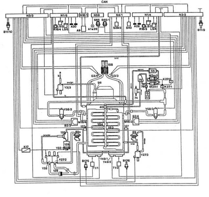
Functional diagram of the injection system of the engine 120
R16 / 2 - Exemplary resistor of the ignition module; R16 / 3 - Exemplary resistor of the left ignition module on the engine 120; R16 / 4 - Exemplary resistor of the right ignition module on the engine 120; S29 / 3 - Limit switch idling; S40 - Tempostat switch; A - Off; B - Overclocking / installation; SP - Reinstall; V - Engine braking / installation; S65 - Transmission overload safety switch (band brake B1); S65/1 - Transmission overload safety switch (band brake B21) . Engine 120; T1 - Ignition coil; T1 / 1 - Ignition coil of the right cylinder head on the engine 120; T1 / 2 - Ignition coil of the left cylinder head on the engine 120; Y3/3 - Pneumatic valve for upshift damper; Y27 - EGR switching valve; Y27 / 2 - Left EGR switch on engine 120; Y27 / 3 - Right EGR switch on engine 120; Y32 - Switching valve for the air mixing pump in the exhaust manifold; Y33 - Electromagnetic clutch of the pump for mixing air into the exhaust manifold; Y49 - Solenoid valve for camshaft adjuster; Y49 / 1 - Solenoid valve for the camshaft regulator of the left cylinder head on the engine 120; Y49 / 2 - Solenoid valve for the camshaft adjuster of the right cylinder head on the engine 120; Y58/1 - Pneumatic switch for carbon adsorber; Y58 / 2 - Left pneumoswitch of the coal adsorber on the engine 120; Y58 / 3 - Right pneumoswitch of the coal adsorber on the engine 120; Y62 - Fuel injectors (left row of cylinders on the engine 120); Y63 - Fuel injectors of the right row of cylinders on the engine 120
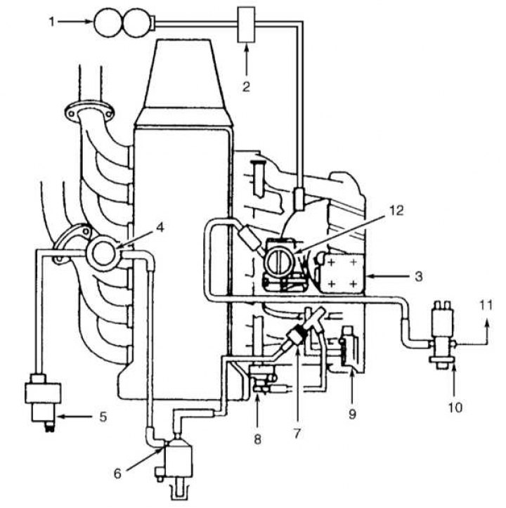
Diagram of laying vacuum lines (engines 104)
1 - Vacuum receiver; 2 - Vacuum distributor; 3 - Resonant damper; 4 - Air cut-off valve (with built-in control valve); 5 - Electric vacuum pump; 6 - Air pump switch valve; 7 - Vacuum control valve; 8 - Diaphragm pressure regulator; 9 - Absolute pressure sensor in the intake manifold (MAP); 10 - Purge control valve; 11 - To the coal adsorber; 12 - Throttle actuator
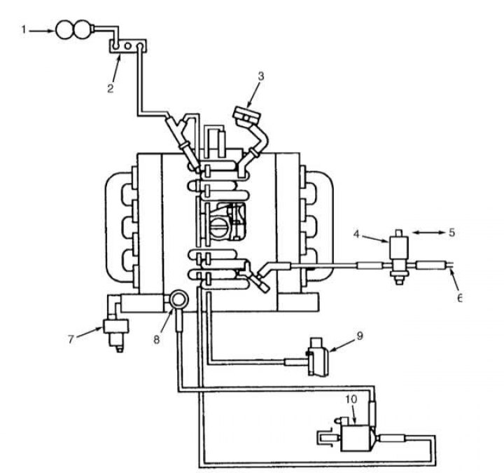
Diagram of laying vacuum lines (engines 119)
1 - Vacuum receiver; 2 - Control valve for vacuum supply; 3 - Diaphragm pressure regulator; 4 - Purge control valve; 5 - To the control module of the ME-SFI injection system; 6 - To the coal adsorber; 7 - Electric air pump; 8 - Valve for shutting off the air supply; 9 - Absolute pressure sensor in the intake manifold (MAP); 10 - Air pump switch valve
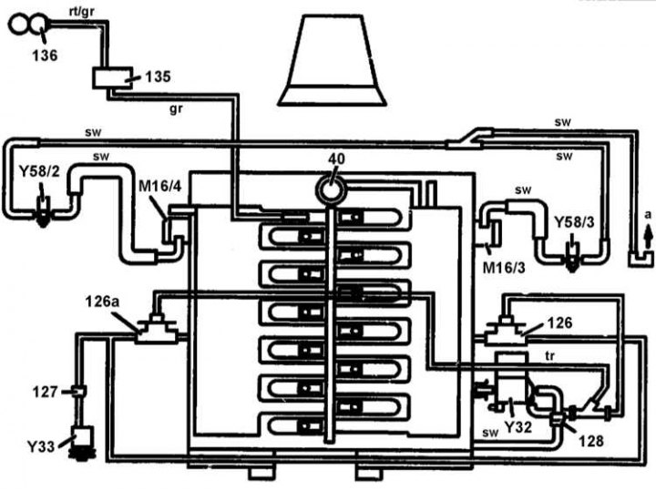
Scheme of connecting vacuum and evaporation lines to the inlet pipeline (engines 120)
40 - Diaphragm pressure regulator; 125 - Air pump; 126 - Air cut-off valve; 126a - Right air shut-off valve; 127 - Left control valve (air mixing); 128 - Vacuum control valve; 135 - Control valve of the vacuum supply line; 136 - Vacuum receiver; M16 / 3 - Left activator of the electronic accelerator / tempostat / idle speed control device. On the left side of the power unit; M16 / 4 - Right activator of the electronic accelerator / tempostat / idle speed control device. On the right side of the power unit; Y32 - Air pump switch valve; Y33 - Air pump electromagnetic clutch; Y58/2 - Left purge control valve; Y58/3 - Right purge control valve; a - to the coal adsorber; rt - red; gr - grey; sw - black; tr - neutral
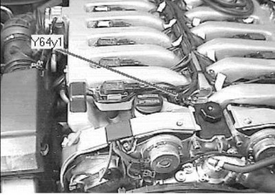
The injector of the first cylinder is located in the right front of the power unit (on the example of a 12-cylinder engine).
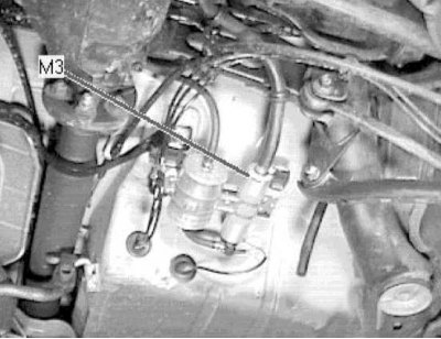
The fuel pump assembly is placed under the vehicle, in front of the right rear axle shaft.
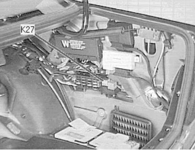
The fuel pump relay is located on the right side of the luggage compartment, behind the rear fuse box.
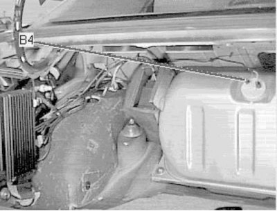
The fuel gauge is located in the left front corner of the luggage compartment, on the fuel tank.
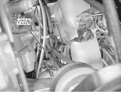
The intake manifold changeover valve is placed under the intake manifold (bottom view).
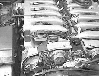
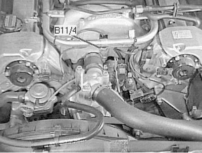
Left thermometric air mass meter (MAF) placed on the right side of the engine compartment, on the air intake sleeve.
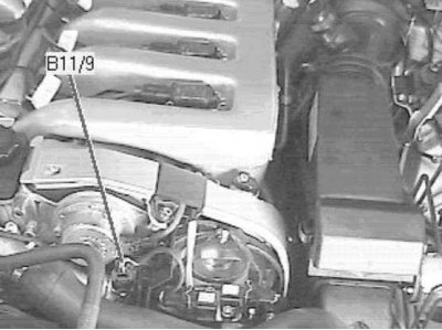
The left coolant temperature sensor is located on the left front of the power unit.
The right coolant temperature sensor is located on the left front of the power unit.
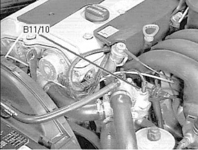
coolant temperature sensor (ECT) located at the top of the left front corner of the power unit.
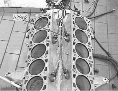
Left knock sensor (KS) located in a recess on top of the engine (The picture shows the engine removed from the car).
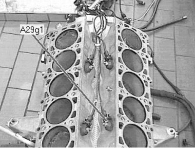
Left knock sensor (KS) 1 is located in a recess on top of the engine (The picture shows the engine removed from the car).
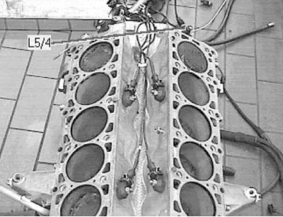
Left Crankshaft Position Sensor (CKP) on the V12 engine, - on the right on the rear wall of the engine block. (The picture shows the engine removed from the car)
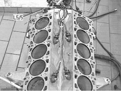
Right crankshaft position sensor (CKP) on the V12 engine, - at the rear at the top of the cylinder block (engine removed from car).
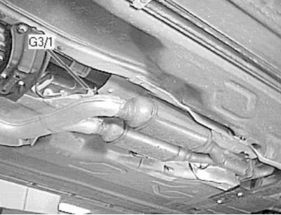
Left pre-catalytic lambda probe 1, - under the car, close to the DP, above the catalytic converter.
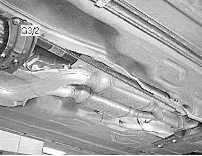
Pre-catalytic lambda probe 1, - under the car, close to the DP, on the tubular section of the exhaust system, in front of the catalytic converter.
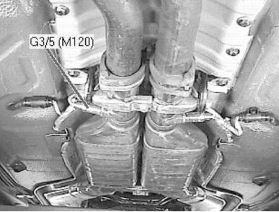
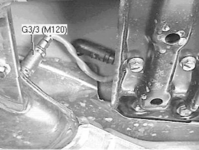
Left post-catalytic lambda probe 2, - under the car, near the DP.
Post-catalytic lambda probe 2, - under the car, near the DP under the rear seat, in the exhaust system pipe behind the catalytic converter.
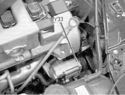
The electromagnetic clutch of the air mixing pump is located at the bottom in the right front corner of the engine compartment.
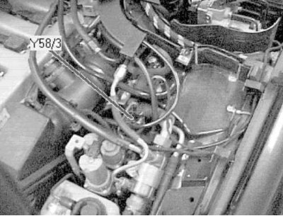
The right canister purge valve is located on the left side of the engine compartment, on the wheel arch mudguard.
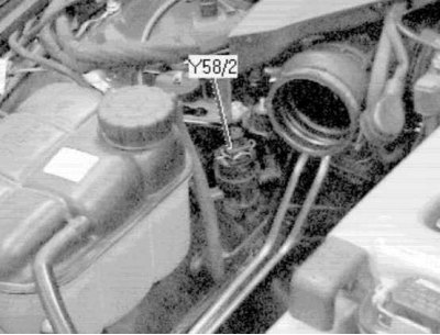
The left canister purge valve is located on the right side of the engine compartment, on the wheel arch mudguard, behind the expansion tank of the cooling system.
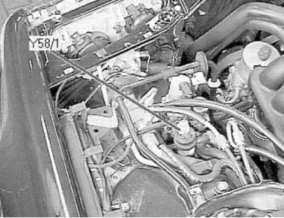
The canister purge valve is located in the left front corner of the engine compartment, on the wheel arch mudguard.
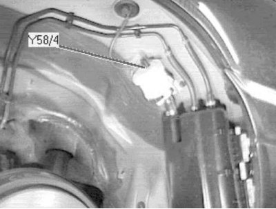
The canister purge shut-off valve is located under the vehicle, at the rear of the left rear wheel arch.