



Drive shafts and differential Mercedes S-Class (W220)
The car is driven by transmitting torque from the gearbox to the wheels using two drive shafts. The anthers of the inner hinges are made of rubber, and the outer ones are made of thermoplastic (thermoplastic is more resistant to external influences). Each shaft consists of three main parts: an internal hinge ("tripod" type), the shaft itself and an external constant velocity joint (CV joint). The outer joints of both shafts (CV joints) end with splined shafts that enter the splined hubs of the drive wheels. The shafts are fixed in the hubs with nuts.

Drive shaft and differential specifications
Note: Individual characteristics are also given in the text of the Chapter and, if their implementation is mandatory, are highlighted in bold. Drive shafts Inner CV...
Note: Individual characteristics are also given in the text of the Chapter and, if their implementation is mandatory, are highlighted in bold. Drive shafts Inner CV...

Removal and installation the propeller shaft
Cardan shaft 2 - Cardan shaft; 5, 21, 200a - Bolts; 6, 20, 36 - Washers; 7, 35, 88, 200 - Nuts; 18 - Engine support; 19 - Engine bracket; 56 - Seal; 87 - Flange Removal...
Cardan shaft 2 - Cardan shaft; 5, 21, 200a - Bolts; 6, 20, 36 - Washers; 7, 35, 88, 200 - Nuts; 18 - Engine support; 19 - Engine bracket; 56 - Seal; 87 - Flange Removal...

Removal and installation the drive shaft flange and radial thrust ball bearing
Removal 1. Remove the drive shaft. 2. Remove the brake disc. 3. Remove the parking brake shoes. 4. Remove the drive shaft flange 10 (with the wheel support installed)....
Removal 1. Remove the drive shaft. 2. Remove the brake disc. 3. Remove the parking brake shoes. 4. Remove the drive shaft flange 10 (with the wheel support installed)....

Drive shaft — removal, inspection and installation
Drive shaft. View of the rear wheel suspension Removal 1. Remove the exhaust system from the flange connection. 2. Remove the cable guide. 3. Disconnect the control...
Drive shaft. View of the rear wheel suspension Removal 1. Remove the exhaust system from the flange connection. 2. Remove the cable guide. 3. Disconnect the control...

Removal and installation of CV joints and protective covers of drive shafts
37a - Drive shaft; 37b - Outer hinge; 37c - Inner hinge; 37d - Joint hub; 37th - Ball; 37f - Separator; 37g - Retaining ring; 37h - Lid; 37i - Oil seal; 37k - Clamp;...
37a - Drive shaft; 37b - Outer hinge; 37c - Inner hinge; 37d - Joint hub; 37th - Ball; 37f - Separator; 37g - Retaining ring; 37h - Lid; 37i - Oil seal; 37k - Clamp;...

Disassembling and assembling the differential
Differential 13 - Differential housing; 14 - Spherical gaskets; 15 - Satellites; 16 - Finger; 17 - Bevel gears of drive shafts; 18 - Thrust washers; 19 - Roller pin...
Differential 13 - Differential housing; 14 - Spherical gaskets; 15 - Satellites; 16 - Finger; 17 - Bevel gears of drive shafts; 18 - Thrust washers; 19 - Roller pin...

Disassembly and assembly of the main gear reducer and adjustment of gear clearances
Disassembly and assembly of the main gear reducer 11a, 43e, 46b. - Outer bearing rings; 11b, 43d, 46a. - Inner bearing ring; 13 - Differential housing; 13a - Bolts; 29,...
Disassembly and assembly of the main gear reducer 11a, 43e, 46b. - Outer bearing rings; 11b, 43d, 46a. - Inner bearing ring; 13 - Differential housing; 13a - Bolts; 29,...

Determining the thickness of the adjusting shim and installing it in the gearbox housing
1. Fix the indicator to the clamp and install the measuring plate (refer to the accompanying illustration). 2. Set the indicator to "0" with 3 mm tension on the...
1. Fix the indicator to the clamp and install the measuring plate (refer to the accompanying illustration). 2. Set the indicator to "0" with 3 mm tension on the...
Checking and adjusting the flange clearance
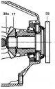
Check the clearance between flange 33 and bevel gear of drive shaft 17. If necessary, install a thinner or thicker retaining ring 30a. The thickness of the retaining...
Check the clearance between flange 33 and bevel gear of drive shaft 17. If necessary, install a thinner or thicker retaining ring 30a. The thickness of the retaining...

Disassembling and assembling a differential with automatic locking
The differential with automatic locking is shown in the illustration: A - Block of friction discs with a driven gear with a diameter of 185 mm. Disassembly Remove roller...
The differential with automatic locking is shown in the illustration: A - Block of friction discs with a driven gear with a diameter of 185 mm. Disassembly Remove roller...
This section is available on: russian, bulgarian, belarusian, ukrainian, serbian, croatian, romanian, polish, slovak, hungarian
More similar sections for repairing other models
☛ Transmission: Drive shafts car Mercedes W124 (1984-1995)
☛ Transmission: Drive shafts and cardan car Mercedes W163 (1997-2005)
Link in different formats to this section
TEXTHTMLBB Code
- General information
- Introduction to guide
- User manual
- Maintenance
- Power unit
- Engine repair
- Cooling and heating systems
- Power and exhaust systems
- Ignition and control system
- Charge and launch systems
- Transmission
- Automatic gearbox
- Drive shafts
- Chassis
- Brake system
- Front suspension
- Rear suspension
- Steering
- Body
- Body elements
- Electrical equipment
- Equipment and devices
- Electrical circuits
- User manual
- Controls and instruments
- Driving and operation
- Maintenance
- Power unit
- Petrol engine V6
- Petrol engine V8
- Petrol engine V12
- Diesel engine OM603
- Diesel engine OM606
- Cooling system
- Power supply and injection system
- Control system HFM-SFI
- Control system LH-SFI
- Control systems ME-SFI
- Diesel control system
- Ignition system
- Charge and launch system
- Transmission
- Mechanical gearbox 717.438
- Mechanical gearbox 717.454
- Automatic gearbox 722.5
- Automatic gearbox 722.6
- Clutch and drive shafts
- Differential
- Chassis
- Brake system
- Steering
- Front suspension
- Rear suspension
- Body
- Exterior (external elements)
- Interior (internal elements)
- Electrical equipment
- Equipment and devices
- Electrical circuits
- General information
- Introduction to guide
- Power unit
- 8-cylinder V8 engine
- 6-cylinder I6 engine
- Cooling and lubrication system
- Power system (carburetor)
- Fuel injection system
- Ignition system
- Transmission
- Clutch and cardan
- Car gearbox
- Chassis
- Front suspension
- Rear suspension
- Steering
- Brake system
- Electrical equipment
- Power devices
- Electrical circuits