



Automatic transmission 722.5 Mercedes S-Class (W140)

Automatic transmission — general information
An automatic transmission, when starting off, performs the function of a regular clutch, and during movement, it performs the work of shifting gears. The main components...
An automatic transmission, when starting off, performs the function of a regular clutch, and during movement, it performs the work of shifting gears. The main components...

Automatic Transmission Specifications
Note: Individual characteristics are also given in the text of the Chapter and, if their implementation is mandatory, are highlighted in bold. General parameters Type...
Note: Individual characteristics are also given in the text of the Chapter and, if their implementation is mandatory, are highlighted in bold. General parameters Type...

Troubleshooting — General Information
If you detect a fault with your automatic transmission, first check the ATF level (see Chapter Routine maintenance ). If the level is insufficient, check the condition...
If you detect a fault with your automatic transmission, first check the ATF level (see Chapter Routine maintenance ). If the level is insufficient, check the condition...

Removal and installation of automatic transmission
AT installation details Removal 1. Disconnect the negative cable from the battery. 2. Press out the ball clutch, squeeze the plastic clip with pliers and remove the gear...
AT installation details Removal 1. Disconnect the negative cable from the battery. 2. Press out the ball clutch, squeeze the plastic clip with pliers and remove the gear...

Removal, condition check and installation of the torque converter
Removal 1. Install the gearbox with the rotation converter facing up. 2. Turn the plastic pin of the rotation converter 1/4 turn counterclockwise. 3. Screw the handles...
Removal 1. Install the gearbox with the rotation converter facing up. 2. Turn the plastic pin of the rotation converter 1/4 turn counterclockwise. 3. Screw the handles...

Removal and installation a centrifugal regulator
Removal Centrifugal Regulator Installation Details 1. Raise the transmission. 2. Remove the engine cross member (19). Remove the exhaust pipe bracket (10) and bracket...
Removal Centrifugal Regulator Installation Details 1. Raise the transmission. 2. Remove the engine cross member (19). Remove the exhaust pipe bracket (10) and bracket...

Removal and installation the starter lock switch sensor
Removal Starter Lock Switch Sensor Installation Details 5 - Retainer; 6, 10 - Bolts; 7 - Nut; 8 - Electrical wiring connector; 9 - Shift rod; 52 - Gear shift lever; 54 -...
Removal Starter Lock Switch Sensor Installation Details 5 - Retainer; 6, 10 - Bolts; 7 - Nut; 8 - Electrical wiring connector; 9 - Shift rod; 52 - Gear shift lever; 54 -...

Installation details of the AT vacuum unit
Installation details of the AT vacuum unit 50 - Bolt; 59 - Pressure modulator; 39a - Finger; 60 - Vacuum unit; A - AT to No.3 800 741; B - AT with No.3 000 742
Installation details of the AT vacuum unit 50 - Bolt; 59 - Pressure modulator; 39a - Finger; 60 - Vacuum unit; A - AT to No.3 800 741; B - AT with No.3 000 742

Removal, maintenance and installation of the secondary pump (AT up to No. 3652931)
Removal Secondary Pump Installation Details (AT to No.3652931) 18, 29 - Sealing rings; 19 - Intermediate plate; 20 - Pump body; 21 - Cut-off piston; 22, 22 - Pump gears;...
Removal Secondary Pump Installation Details (AT to No.3652931) 18, 29 - Sealing rings; 19 - Intermediate plate; 20 - Pump body; 21 - Cut-off piston; 22, 22 - Pump gears;...

Removal and installation the front cover with secondary pump
Removal Front Cover Installation Details with Secondary Pump 1. Loosen the bolts (18). 2. Remove the front cover (10) by unscrewing the two bolts (18) (arrows)....
Removal Front Cover Installation Details with Secondary Pump 1. Loosen the bolts (18). 2. Remove the front cover (10) by unscrewing the two bolts (18) (arrows)....

Removal and installation the LB3 piston
Removal 1. Remove the Teflon rings (9) from the grooves in the front cover. 2. Place the puller (020) on the spring sleeve (13) and compress it until the retaining ring...
Removal 1. Remove the Teflon rings (9) from the grooves in the front cover. 2. Place the puller (020) on the spring sleeve (13) and compress it until the retaining ring...

Removal and installation the rear transmission cover
Transmission Rear Cover Installation Details Removal 1. Remove the drain plug (4a) and drain the ATF. 2. Raise the gearbox. 3. Remove the engine cross member. 4. Remove...
Transmission Rear Cover Installation Details Removal 1. Remove the drain plug (4a) and drain the ATF. 2. Raise the gearbox. 3. Remove the engine cross member. 4. Remove...
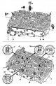
Disassembly and assembly of the AT valve assembly
Disassembly Design of the AT valve assembly 1 - Gear shift valve; 7 - Blocking valve K1; 9 - Bypass valve without hole (white); 13 - Reed check valve with hole; 14 -...
Disassembly Design of the AT valve assembly 1 - Gear shift valve; 7 - Blocking valve K1; 9 - Bypass valve without hole (white); 13 - Reed check valve with hole; 14 -...

Disassembly and assembly of the transmission
Section 1 Disassembly Transmission Component Installation Details (Section 1) 3 - AT oil pan; 3a - Gasket; 4, 7, 8, 108, 140 - Bolts; 5 - Oil filter; 13 - Bottom cover;...
Section 1 Disassembly Transmission Component Installation Details (Section 1) 3 - AT oil pan; 3a - Gasket; 4, 7, 8, 108, 140 - Bolts; 5 - Oil filter; 13 - Bottom cover;...

Installation and clearance check in B3 multi-disc brake
Installation B3 Multi-Disc Brake Disc Arrangement 133b - Internal disk; 133a - Outer disk; 85 - Disc spring; 10 - Brake piston B3 Place the B3 multi-disc brake discs in...
Installation B3 Multi-Disc Brake Disc Arrangement 133b - Internal disk; 133a - Outer disk; 85 - Disc spring; 10 - Brake piston B3 Place the B3 multi-disc brake discs in...

Measuring the Brake Clearance B1
Preparation 1. Insert the radial oil seal (39) into the B1 brake piston (37). 2. Insert the pin with the gaskets and sealing ring into the B1 brake piston. The sealing...
Preparation 1. Insert the radial oil seal (39) into the B1 brake piston (37). 2. Insert the pin with the gaskets and sealing ring into the B1 brake piston. The sealing...

Overdrive clutch
Disassembly Overdrive clutch design 172 - Multi-plate clutch support; 174, 179 - Retaining rings; 180 - Spring disc; 181, 185 - Radial oil seals; 182 - Spring; 183 -...
Disassembly Overdrive clutch design 172 - Multi-plate clutch support; 174, 179 - Retaining rings; 180 - Spring disc; 181, 185 - Radial oil seals; 182 - Spring; 183 -...

Removal, installation and inspection of BS overdrive brake and KS clutch components
Removal BS brake overdrive and KS clutch design 86 - Output shaft; 163, 186, 190 - Locking rings; 166 - Gaskets; 168 - Driver; 169 - Thrust bearing; 170 - Ring gear; 171...
Removal BS brake overdrive and KS clutch design 86 - Output shaft; 163, 186, 190 - Locking rings; 166 - Gaskets; 168 - Driver; 169 - Thrust bearing; 170 - Ring gear; 171...

Disassembly and assembly of the freewheel clutch
Freewheel clutch design 1 - Crown gear; 2, 4 - Retaining rings; 3 - Gasket; 5 - Sealing ring; 6 - Roller bearing; 9 - Inner ring of the coupling; 10 - Outer ring of the...
Freewheel clutch design 1 - Crown gear; 2, 4 - Retaining rings; 3 - Gasket; 5 - Sealing ring; 6 - Roller bearing; 9 - Inner ring of the coupling; 10 - Outer ring of the...

Disassembly and assembly of planetary mechanisms
Disassembly Planetary gear design 2 - Front planetary gear; 3 - Retaining ring; 4, 6, 8, 23 - Thrust bearings; 5, 9 - Radial bearings; 7 - Connecting support; 10 - Sun...
Disassembly Planetary gear design 2 - Front planetary gear; 3 - Retaining ring; 4, 6, 8, 23 - Thrust bearings; 5, 9 - Radial bearings; 7 - Connecting support; 10 - Sun...

Disassembly and assembly of the K1 clutch
Disassembly Clutch design K1 1 - Outer disc support; 2 - Piston; 3 - Spring; 4 - Spring bushing; 5, 11, 16 - Retaining rings; 6 - Inner disk; 7, 8, 10 - Outer disks; 12,...
Disassembly Clutch design K1 1 - Outer disc support; 2 - Piston; 3 - Spring; 4 - Spring bushing; 5, 11, 16 - Retaining rings; 6 - Inner disk; 7, 8, 10 - Outer disks; 12,...

Clutch K2 — disassembly, assembly and inspection
Disassembly Clutch design K2 1 - Outer disc support; 2 - Piston; 3 - Spring; 4 - Spring bushing; 5, 11 - Retaining rings; 6 - Inner disk; 8, 10 - Outer disks; 12, 13 -...
Disassembly Clutch design K2 1 - Outer disc support; 2 - Piston; 3 - Spring; 4 - Spring bushing; 5, 11 - Retaining rings; 6 - Inner disk; 8, 10 - Outer disks; 12, 13 -...

Gear selector lever
Removal Gear Selector Lever Installation Details 1 - Body; 2 - Gear selector lever; 6, 42 - Bolts; 10 - Gear shift rod; 40B, 40L - Cables; 41 - Clamp; 49 - Retainer;...
Removal Gear Selector Lever Installation Details 1 - Body; 2 - Gear selector lever; 6, 42 - Bolts; 10 - Gear shift rod; 40B, 40L - Cables; 41 - Clamp; 49 - Retainer;...
This section is available on: russian, bulgarian, belarusian, ukrainian, serbian, croatian, romanian, polish, slovak, hungarian
More similar sections for repairing other models
☛ Transmission: Automatic gearbox car Mercedes W203 (2000-2007)
☛ Transmission: Automatic gearbox car Mercedes W210 (1996-2002)
☛ Transmission: Automatic gearbox car Mercedes W463 (1999-2019)
☛ Transmission: Automatic gearbox car Mercedes W163 (1997-2005)
☛ Transmission: Automatic gearbox 723.345 car Mercedes Vario 814D (1996-2003, diesel)
Link in different formats to this section
TEXTHTMLBB Code
- General information
- Introduction to guide
- User manual
- Maintenance
- Power unit
- Engine repair
- Cooling and heating systems
- Power and exhaust systems
- Ignition and control system
- Charge and launch systems
- Transmission
- Automatic gearbox
- Drive shafts
- Chassis
- Brake system
- Front suspension
- Rear suspension
- Steering
- Body
- Body elements
- Electrical equipment
- Equipment and devices
- Electrical circuits
- User manual
- Controls and instruments
- Driving and operation
- Maintenance
- Power unit
- Petrol engine V6
- Petrol engine V8
- Petrol engine V12
- Diesel engine OM603
- Diesel engine OM606
- Cooling system
- Power supply and injection system
- Control system HFM-SFI
- Control system LH-SFI
- Control systems ME-SFI
- Diesel control system
- Ignition system
- Charge and launch system
- Transmission
- Mechanical gearbox 717.438
- Mechanical gearbox 717.454
- Automatic gearbox 722.5
- Automatic gearbox 722.6
- Clutch and drive shafts
- Differential
- Chassis
- Brake system
- Steering
- Front suspension
- Rear suspension
- Body
- Exterior (external elements)
- Interior (internal elements)
- Electrical equipment
- Equipment and devices
- Electrical circuits
- General information
- Introduction to guide
- Power unit
- 8-cylinder V8 engine
- 6-cylinder I6 engine
- Cooling and lubrication system
- Power system (carburetor)
- Fuel injection system
- Ignition system
- Transmission
- Clutch and cardan
- Car gearbox
- Chassis
- Front suspension
- Rear suspension
- Steering
- Brake system
- Electrical equipment
- Power devices
- Electrical circuits