
Removing
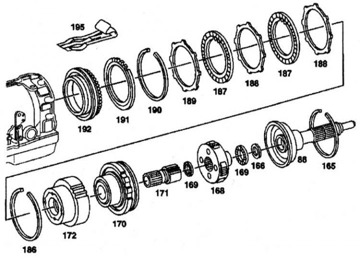
Construction of overdrive brake BS and clutch KS
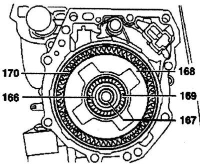
86 - Output shaft; 163, 186, 190 - Blocking rings; 166 - Gaskets; 168 - carrier; 169 - Thrust bearing; 170 - Crown gear; 171 - Sun gear; 172 - Overdrive clutch; 187 - Internal disk; 188, 189 - Outer discs; 191 - Cam spring; 192 - Overdrive brake piston; 195 - Damper spring
1. Remove the gearbox rear cover.
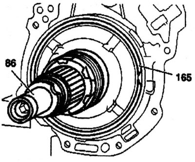
2. Remove the drive shaft (86), by removing the retaining ring (165).
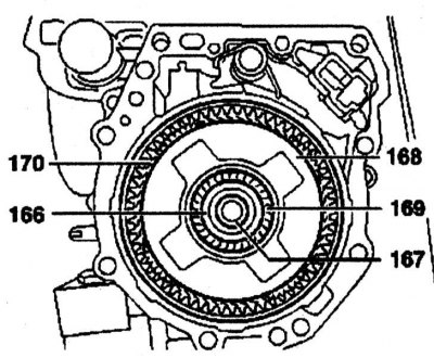
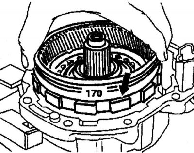
3. Remove the ring gear (170). Remove gaskets (166) and thrust bearing (169) from the output shaft (167). Remove carrier (168) from ring gear (170).
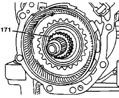
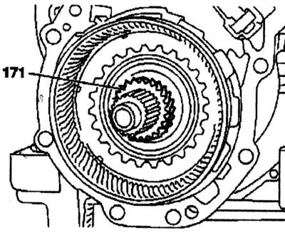
4. Remove sun gear (171) and ring gear (170).
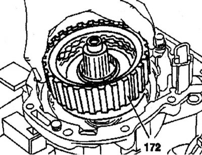
5. Remove the overdrive clutch (172) with disk block.
6. Remove the overdrive brake disc assembly from the housing by removing the circlip (186).
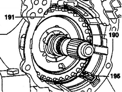
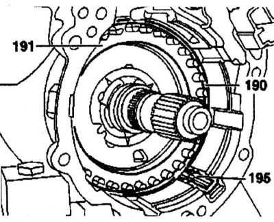
7. Remove damper spring (195). Remove locking ring (190) and cam spring (191).
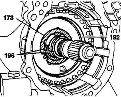
8. Using pliers, remove the overdrive brake piston (192) from the housing, remove the Teflon rings (196), and then the thrust washer (173).
Installation
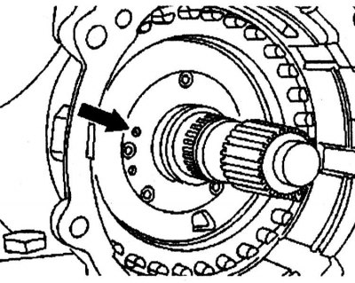
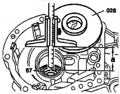
1. Before installing the thrust washer (173) make sure the oil hole (arrow) installed in the gearbox housing.
2. Lubricate both O-rings of the overdrive brake piston (192) gear oil, press the piston into the body, insert the thrust washer (173) so that the anti-rotation lip is in the housing, screw in the Teflon rings (196).

3. Insert the cam spring (191), install the blocking ring (190), install damper spring (195). Install overdrive brake discs individually.
4. Carefully insert the overdrive clutch support (17) into a multi-disc overdrive brake.
5. Carefully insert the ring gear (170) to the overdrive brake.
6. Insert sun gear (171).
7. Insert carrier (168) into the ring gear (170), make sure the inner thrust bearing is (169) grabbed the carrier, fix the outer thrust bearing (169), install gaskets (166) to the output shaft (167).
Checking the axial clearance between the output and intermediate shafts
1. Measure the distance «a» from the contact surface of the output shaft bearing (86) to the inner ring of the bearing (198) using a caliper.
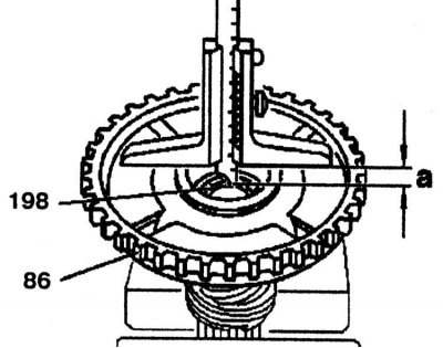
2. Determine the distance «b» from gaskets (166) to roller thrust bearing (169) using a caliper.
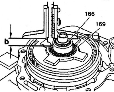
3. Adjust axial clearance «With» gaskets (166), by determining the thickness of the gasket:
Distance «a» (18.00 mm) - Distance «b» (16.60 mm) = Difference (1.40 mm) - Axial clearance (0.10 mm) - Gasket thickness (1.30 mm).
Axial clearance between output and intermediate shafts 0.10 mm. Gaskets are available in thicknesses of 0.1, 0.2 and 0.5 mm.
4. Install the output shaft (86) and insert the locking ring (165).
Checking the axial clearance between the output shaft and the rear cover
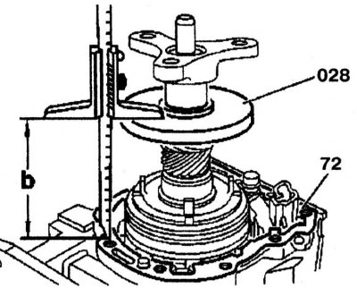
1. Measure the distance «a», by installing the measuring disk (028) on the contact surface of the back cover. Determine the distance from the disk (028) to the inner race of the ball bearing (67) and using a caliper.
2. Install the measuring disc (028) and flange. Lock the parking brake pawl in the working position. tighten the nut (62) up to 100 Nm. Install gasket (72).
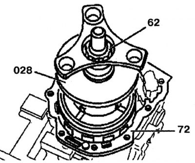
3. Measure the distance «b» between the measuring disc (028) and gasket (72).
4. Adjust axial clearance «E» gaskets:
Distance «a» (118.80 mm) - Distance «b» = Difference (1.90 mm) - Axial clearance «E» (0.40 mm) = Gasket thickness (1.50 mm).
The nominal end play between the output shaft and the rear cover is 0.40 mm. Gaskets are available in thicknesses of 0.5, 0.6, 0.7, 0.8 and 0.9 mm.
5. Remove the measuring disc and flange.
Overdrive Brake Clearance Check
Overdrive Brake Clearance Check
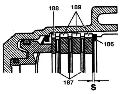
186 - Retaining ring; 187 - Internal disk; 188, 189 - Outer disc
1. Measure the clearance «S». The nominal clearance of the overdrive brake is within the range of 0.5-1.1mm. Adjust it if necessary with the circlip shims (186). Gaskets are available in thicknesses of 2.0, 2.5 and 3.0 mm.
2. Install the gearbox rear cover.