
111 Series Engine Crankshaft Sprocket Installation Details
111 Series Engine Cylinder Head Installation Details
M111
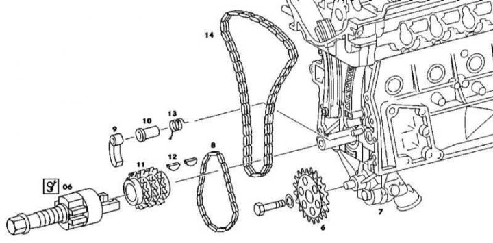
Crankshaft sprocket
1. Installation details of the 111 series crankshaft sprocket are shown in the illustration, to which all references in the text refer.
2. Remove the oil pan (see Section Maintenance of the lubrication system).
3. Remove the timing cover (see Section Removing and installing timing covers).
4. Loosen the sprocket (6) oil pump drive, or remove the pump assembly (see Section Maintenance of the lubrication system).
5. Remove the oil pump drive chain (8).
6. Remove the timing chain (see Section Replacing the gas distribution chain), - for throwing off the chain from the crankshaft sprocket (11) move the tensioner bar aside.
7. Using a puller (06) dismantle the crankshaft sprocket (11).
8. Installation is carried out in the reverse order. If necessary, the sprocket should be warmed up before landing on the shaft trunnion, also make sure that the segment keys fit correctly (12) into the receiving slot. Chain guide on cylinder head
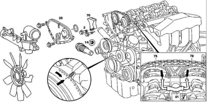
9. The details of installing the chain guide on the cylinder head of the 111 series engine are shown in the illustration, to which all references in the text refer.
10. Remove front cover (23) cylinder heads (see Section Removing and installing timing covers).
11. Turning the crankshaft in the normal direction, bring the piston of the first cylinder to a position of 20°after TDC.
12. With locking pins (01) fix the inlet (75) and graduation (78) distribution shafts.
13. Remove chain tensioner (14) (see below).
14. Loosen and remove the chain guide (70).
15. Installation is carried out in the reverse order.
Chain guides on the timing cover
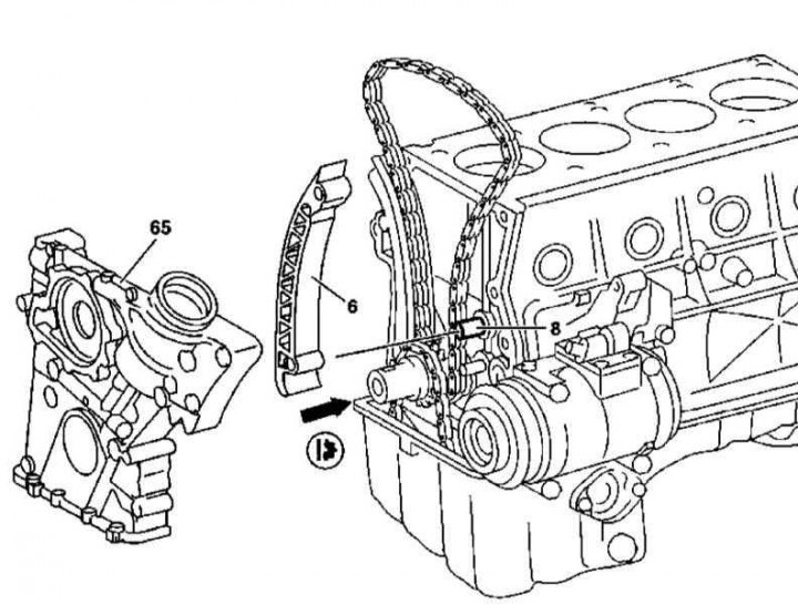
Details of installing the chain guide on the timing cover of the 111 series engine
1. The details of installing the chain guide on the timing cover of the 111 series engine are shown in the illustration, to which all references in the text refer.
2. Remove the cylinder head (see Section Removing and installing the head (OK) cylinders).
3. Remove the timing cover (65) (see Section Removing and installing timing covers).
Note. There is no need to remove the oil pan - take care not to damage the oil pan gasket.
4. Remove the chain guide (6) from bearing pin (8).
5. Installation is carried out in the reverse order.
Chain tensioner
111 Series Timing Chain Tensioner Installation Details
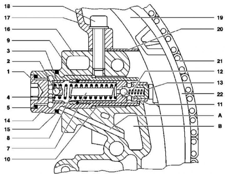
111 series engine timing chain tensioner design
1 - Plug; 2 - Return flow control valve ball; 3 - Spring; 4 - Ball guide; 5 - Aluminum sealing element; 7 - Stock; 8 - Spring; 9 - Spring-loaded latch; 10 - Emphasis; 11 - The ball of the pressure reducing valve; 12 - Spring; 13 - Emphasis (pressed in); 14 - Tensioner housing; 15 - Aluminum sealing element; 16 - Tensioner housing cover; 17 - Cylinder head; 18 - Bolt with washer; 19 - Tension bar; 20 - Cylinder head gasket; 21 - Gas distribution chain; 22 - Plastic friction lining of the bar; A - Oil supply channel; B - Tensioner oil reservoir
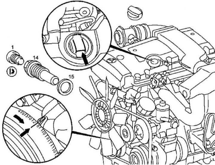
1. Installation details and design features of the 111 series engine timing chain tensioner are shown in the illustrations, which include all references in the text.
2. Remove the air cleaner cover (see chapter Removal and installation of components of an inlet air path).
3. On models equipped with a pressurized air system, remove the compressor.
4. To prevent the chain from jumping when it is removed by the crankshaft sprockets, turn the crankshaft in the normal direction and bring the piston of the first cylinder to a position of 20°after TDC, - the intake valve drive cam visible through the oil filler neck (26) should turn with the working ledge upwards at an angle, - remove the cover (25).
5. Wrap a clean cloth around the generator.
6. Loosen the end cap (1) and remove the tensioner (14).
7. Installation is carried out in the reverse order - do not forget to replace the sealing element (15).
8. Finally, start the engine and check the tensioner assembly for signs of leak development.
Tension bar
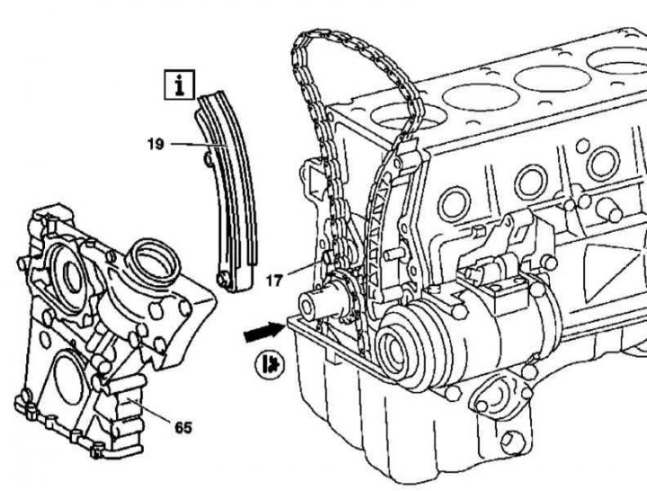
Tension bar installation details on 111 series engine
1. The details of installing the tensioner bar on the 111 series engine are shown in the illustration, to which all references in the text refer.
2. Remove the cylinder head (see Section Removing and installing the head (OK) cylinders).
3. Remove the timing cover (65) (see Section Removing and installing timing covers).
Note. There is no need to remove the oil pan - take care not to damage the oil pan gasket.
4. Remove tension bar (19) from bearing pin (17).
5. Installation is carried out in the reverse order.
M112/113
Chain guides on the timing cover
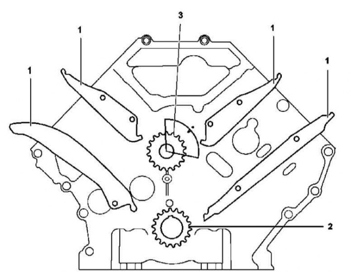
Installation details of the chain guides on the timing cover of the 112 and 113 series engines
1 - Chain guides; 2 - Crankshaft; 3 - Balance shaft
1. The installation details of the timing chain guides on the 112 and 113 series engines are shown in the illustration, which includes all references in the text.
2. Remove powertrain trim panels.
3. If necessary, remove the crankcase protection (see chapter Body).
4. On models equipped with engine 113.942 (ML 230), remove the air baffle.
5. Drain the engine oil (see chapter Changing the engine oil and oil filter).
6. Remove cylinder heads (see Section Removing and installing the head (OK) cylinders).
7. Remove the lower section of the oil pan (see Section Maintenance of the lubrication system).
8. Remove the timing cover (see Section Removing and installing timing covers).
9. Simultaneously removing from the fixing bolts, dismantle the guide chains (1).
10. Installation is carried out in the reverse order.
Chain tensioner
M112/113 (except М113.965/981)
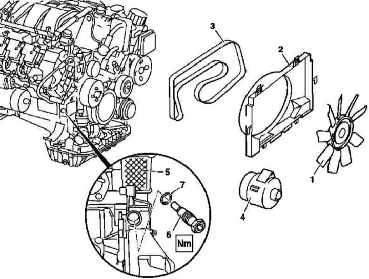
112 and 113 series engine chain tensioner installation details (except 113.965/981)
1. Parts for installing the chain tensioner on 112 and 113 series engines (except 113.965/981) shown in the illustration, which includes all references in the text.
2. Remove the viscous cooling fan assembly (1).
3. Remove fan shroud (2).
4. Remove the accessory drive belt (3).
5. Remove generator (4) (see chapter Engine Electrical Systems).
6. Remove tensioner (6) from the timing cover (5).
7. Installation is carried out in the reverse order - do not forget to replace the sealing element.
М113.965/981
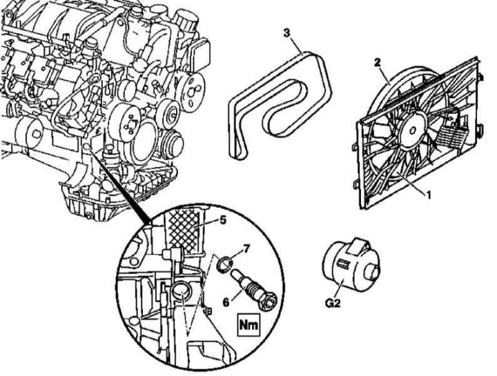
Engine chain tensioner installation details 113.965/981
1. The details of installing the chain tensioner on engines 113.965/981 are shown in the illustration, which includes all references in the text.
2. Remove fan assembly (2 and 1).
3. Remove generator (G2) (see chapter Engine Electrical Systems).
4. Remove tensioner (6) from the timing cover (5).
5. Installation is carried out in the reverse order - do not forget to replace the sealing element (7).