
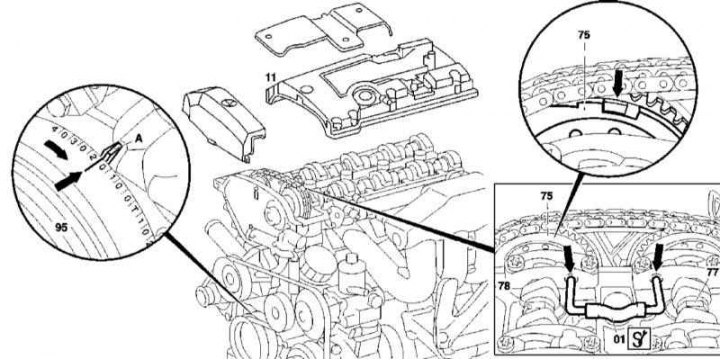
Checking the basic position of the camshafts of the 111 series engine
1. Illustrative material for checking the basic position of the camshafts of the 111 series engine is presented in the illustration, which includes all references in the text.
2. Remove the cylinder head cover (11).
3. Having turned the crankshaft in the normal direction, bring the piston of the first cylinder to the position of 20°after TDC, - mark 20°of the measuring scale on the vibration damper (95) must match pointer (A) on the timing cover, and the intake drive cams (78) and graduation (77) valves of the first cylinder - turn the working projections up at an angle.
4. Check the freedom of passage of the locking rod (01) into the No. 1 or No. 6 bearing cap holes and locking holes of the intake or exhaust camshaft.
5. Due to the tension of the gas distribution chain, the intake camshaft should be between 20 and 30 degrees, and the exhaust camshaft between 25 and 35 degrees after TDC.
Note. A 1-tooth shift in chain seat results in a 20-degree shift - adjust accordingly if necessary (see below).
6. With the correct basic setting, the stop on the sprocket (75) intake camshaft should be offset to the side «delays», i.e. be shifted in the flange recess in the direction of rotation of the camshaft (arrow).
7. Reinstall the removed components in reverse order of removal.
Installation
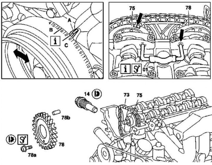
Setting the basic position of the camshafts of the 111 series engine
1. Illustrative material for adjusting the basic position of the camshafts of the 111 series engine is presented in the illustration, which includes all references in the text.
2. Check the basic setting of the camshafts (see above).
3. Remove the front cylinder head cover (see Section Removing and installing timing covers).
4. Having turned the crankshaft in the normal direction, bring the piston of the first cylinder to a position of 30°after TDC, - in this position of the engine, the camshafts can be rotated without the risk of collision of valves with pistons.
5. Remove chain tensioner (14) (see Section Removal and installation of timing drive components).
6. Remove the sprocket (78) exhaust camshaft.
7. Pull up to remove the timing chain (73) from an asterisk (75) intake camshaft.
8. Turn the camshafts to the basic position and fix them with the locking pins (01), threaded through the holes in the bearing caps Nos. 1 and 6.
9. Pulling the chain up, return the piston of the first cylinder to the position 20°after TDC.
10. Put on the chain (73) on an asterisk (75) intake camshaft, after making sure that the position of the latter is correct.
11. After tucking into the chain, reinstall the sprocket (78) exhaust shaft.
12. Install the chain tensioner (14) (see Section Removal and installation of timing drive components).
13. Remove the locking bars (01).
14. Make sure the basic settings are correct (see above).
M112/113
Check and installation
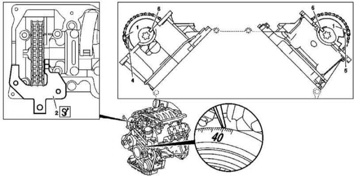
Setting the basic position of the camshafts of the 112 and 113 series engines
1. Illustrative material for adjusting the basic position of the camshafts of engines of the 112 and 113 series is presented in the illustration, which includes all references in the text.
2. Remove the cylinder head covers.
3. Check the correctness of the basic position of the camshafts, - if necessary, turn the engine to a position of 40°after the TDC of the piston of the first cylinder.
4. Remove chain tensioner (see Section Removal and installation of timing drive components).
5. Remove the Hall sensor.
6. Having lifted a chain, remove an asterisk at first right, then the left camshaft.
7. Using an open-end wrench, turn the left camshaft to the base position, - the grooves turned to the diametrical plane of the engine (6) must align with the joint line of the caps with the heads, - and fix it with a blocking plate (2), putting the latter flush with the left head and tucking it into the groove (6) camshaft.
Note. In the position of the piston of the first cylinder 40°after TDC, the camshaft can be rotated without the risk of pistons colliding with the valves.
8. Acting in a similar manner, expose the right camshaft.
9. When refueling the chain, reinstall the camshaft sprockets (first left, then right).
10. Install the Hall sensor.
11. Install chain tensioner (see Section Removal and installation of timing drive components).
12. Make sure that the alignment marks are correctly aligned, then reinstall the cylinder head covers.