
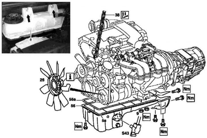
111 Series Engine Sump Installation Details
1. The installation details of the oil pan on the 111 series engine are shown in the illustration, to which all references in the text refer.
2. Drain the engine oil (see chapter Changing the engine oil and oil filter).
3. Remove the viscous cooling fan assembly (26).
4. Unbolt the expansion tank from the bulkhead of the engine compartment (8) cooling systems.
5. Turn out bolts (9) fastening the pillows of the front supports of the power unit to the vehicle frame (see Section Removal and installation of suspension mounts of the power unit).
6. Hang the engine on the winch.
7. Disconnect the oil level sensor wiring (S43).
8. Turn out fixing bolts and remove the pallet of a case (56).
9. Thoroughly clean the mating surfaces and install a new seal on the pallet (56a).
10. Installation is carried out in the reverse order.
Note. Temporary fixation of the pallet to the block can be done using spotted sealant.
Removal and installation of the oil level sensor
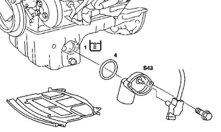
Oil level sensor installation details (3) 111 series engine
1 - Engine oil
4 - O-ring
The installation details of the 111 series engine oil level sensor are shown in the illustration, to which all references in the text refer.
Removal and installation of the oil pump
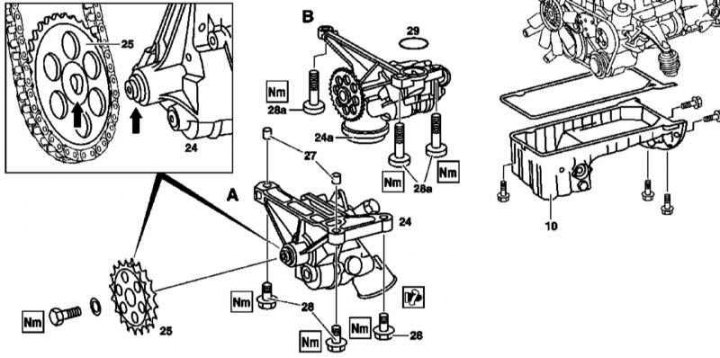
111 Series Engine Oil Pump Installation Details
1. The installation details of the 111 series engine oil pump are shown in the illustration, to which all references in the text refer.
2. Remove the oil pan (see above).
3. Remove the sprocket (25) oil pump drive assembly with a chain thrown over it.
4. Turn out fixing bolts (28/28a) and remove the pump assembly (24/24a).
5. Thoroughly clean the mating surfaces of the pump and motor block.
6. Fill pump assembly with fresh oil.
7. Installation is carried out in the reverse order. When installing the first version pump, note that the two front bolts (28) equipped with guide bushings (27). On pumps of the second version, do not forget to replace the sealing ring (29).
Note. The asterisk is installed with a ledge to the pump.
Replacing the oil pump drive chain
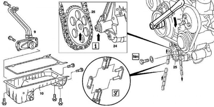
Installation details of the oil pump drive chain on the 111 series engine
1. The installation details of the oil pump drive chain on the 111 series engine are shown in the illustration, which includes all references in the text.
2. Empty the cooling system (see chapter Checking the cooling system and frost resistance of the coolant, changing the fluid).
3. Drain the engine oil (see chapter Changing the engine oil and oil filter).
4. Remove the liquid heat exchanger (9).
5. Remove the oil pan (10) (see above).
6. Remove the oil pump (see above).
7. Using a special tool, dismember the pump drive chain and remove it from the engine.
8. Remove the oil pump drive sprocket (25).
9. Installation is carried out in the reverse order - use a special tool to articulate the chain.
Non-return valve replacement
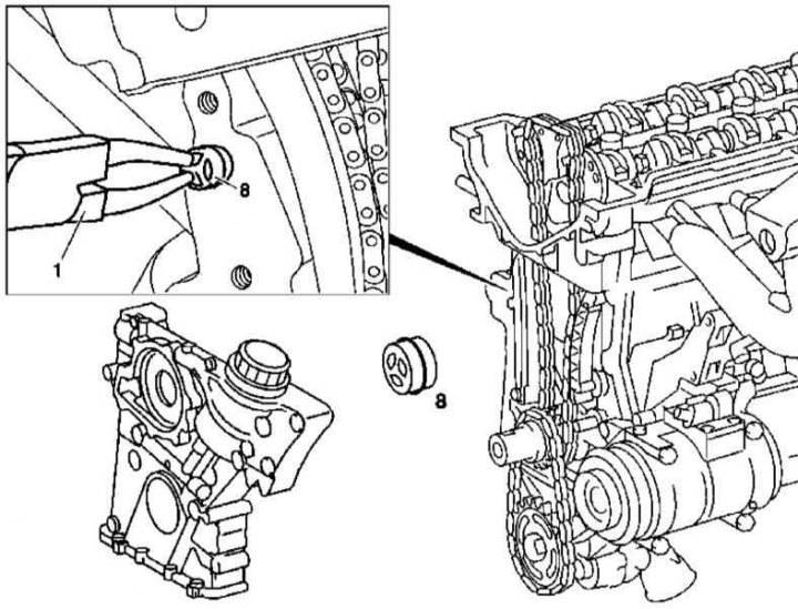
111 Series Engine Oil Check Valve Installation Details
1. Installation details of the non-return valve of the 111 series engine lubrication system are shown in the illustration, to which all references in the text refer.
2. Remove the timing cover (see Section Removing and installing timing covers).
3. Using tongs (1) remove non-return valve (8) from its seat in the engine crankcase.
4. Installation is carried out in the reverse order.
M112/113
Removal and installation of an oil filter casing
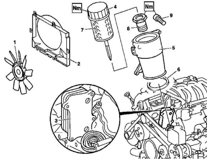
112 and 113 series engine oil filter installation details (on the example of models equipped with a viscous cooling fan)
6 - O-ring
7 - Filter element
8 - Bolt
1. Details of installing the oil filter on engines of the 112 and 113 series are shown in the illustration, to which all references in the text refer.
2. Remove the front cover of the power unit.
3. Remove the powertrain trim panel/air cleaner.
4. Remove fan assembly (1) and fan shroud (2), - on the ML 55 AMG and ML 500 models, remove the electric fan assembly with the shroud.
5. Unscrew the cover (4) casing (5) oil filter.
6. Turn out bolts (9) fixing the liquid heat exchanger (3) to casing (5) oil filter.
7. Remove the cover (5).
8. Installation is carried out in the reverse order.
9. Finally, check the engine oil level, if necessary, make the appropriate adjustment (see chapter Changing the engine oil and oil filter).
Removal and installation of the liquid heat exchanger of the oil filter
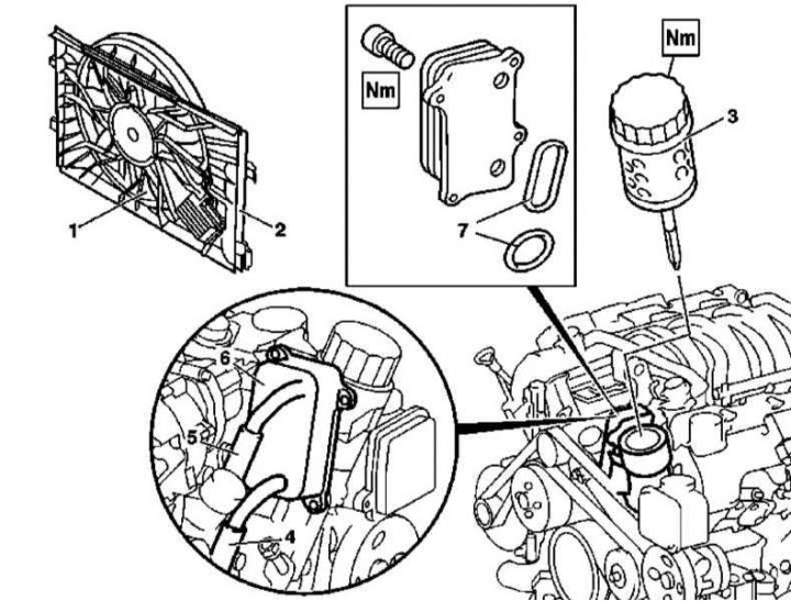
Installation details of the oil filter liquid heat exchanger on 112 and 113 series engines (on the example of engines equipped with an electric cooling fan)
7 - Sealing elements
1. Installation details of the oil filter liquid heat exchanger on 112 and 113 series engines are shown in the illustration, to which all references in the text refer.
2. Follow the procedures described in paragraphs 1 to 5 of Removal and installation of the oil filter housing, correcting for changes in the designations in the illustration.
3. Drain the coolant from the radiator (see chapter Checking the cooling system and frost resistance of the coolant, changing the fluid).
4. Disconnect from liquid heat exchanger (6) cooling path lines (4 and 5).
5. When equipped (ML 55 AMG and ML 500 models) remove the air pump assembly (see Section Removing and installing timing covers).
6. Turn out fixing bolts and remove assembly of the heat exchanger (6) from the filter housing.
7. Installation is carried out in the reverse order.
8. In conclusion, make sure that there are no signs of the development of coolant leaks.
Removal and installation of the guide tube of the dipstick for measuring impellent oil
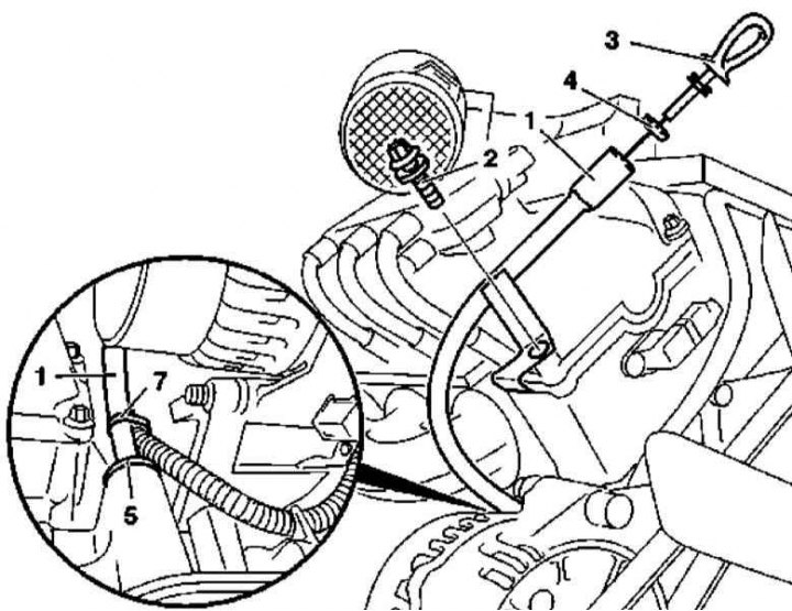
Installation details of the dipstick for measuring the level of impellent oil on models with engines of the 112 and 113 series
4 - O-ring
5 - Sealing washer
1. Installation details of the dipstick guide tube on 112 and 113 series engines are shown in the illustration, to which all references in the text refer.
2. Remove the crankcase protection (see chapter Body).
3. Remove powertrain trim panels/air cleaner assembly.
4. Remove the bolt (2) guide tube mounting (1) probe (3) to the cylinder head.
5. Remove the bandage tape (7).
6. Pull up to remove the handset (1) from the engine.
7. Installation is carried out in the reverse order.
Removal and installation of the oil pan
Bottom section of pallet
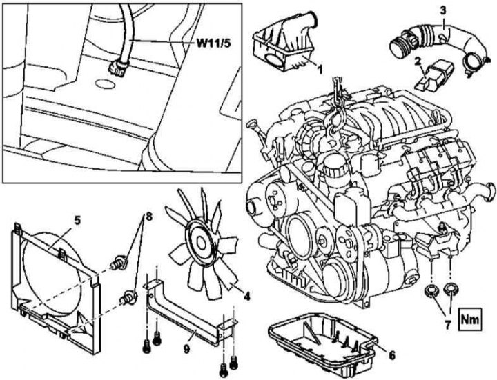
112 and 113 series lower sump installation details
W11 / 5 - Ground bus engine / body
1. Installation details of the lower section of the oil pan on engines of the 112 and 113 series are shown in the illustration, to which all references in the text refer.
2. Remove powertrain trim panel and air cleaner (1).
3. Remove the viscous cooling fan assembly (4).
4. Turn out bolts (8) and remove the fan assembly shroud (5).
5. Remove the air baffle (9).
6. Drain the engine oil (see chapter Changing the engine oil and oil filter).
7. Give nuts (7) fastening the front suspension support of the power unit.
8. Remove the resonator chamber (2) with connecting sleeve (3).
9. Hang the engine on the winch.
10. Turn out fixing bolts and remove the bottom section of the pallet of a case (6).
11. Thoroughly clean the mating surfaces.
12. Installation is carried out in the reverse order.
Note. The pallet is installed on the sealant, which should be applied with a pad 2.0 wide and 0.5 mm thick.
Upper pallet section
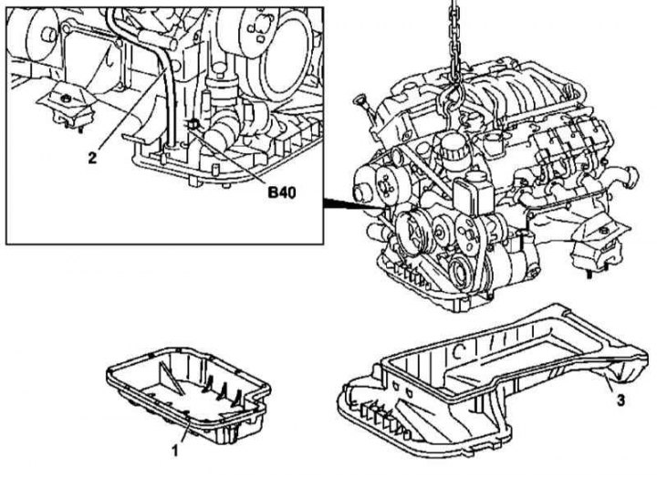
112 and 113 Series Upper Sump Installation Details
1. Details of the installation of the upper section of the oil pan on engines of the 112 and 113 series are shown in the illustration, to which all references in the text refer.
2. Remove the lower section of the oil pan (1) (see above).
3. Disconnect wiring from level/temperature/oil quality sensor (B40).
4. Sliding forward, remove the upper section of the oil pan (3), - turn the crankshaft slightly if necessary.
5. Installation is carried out in the reverse order.
Removal and installation of the oil level sensor
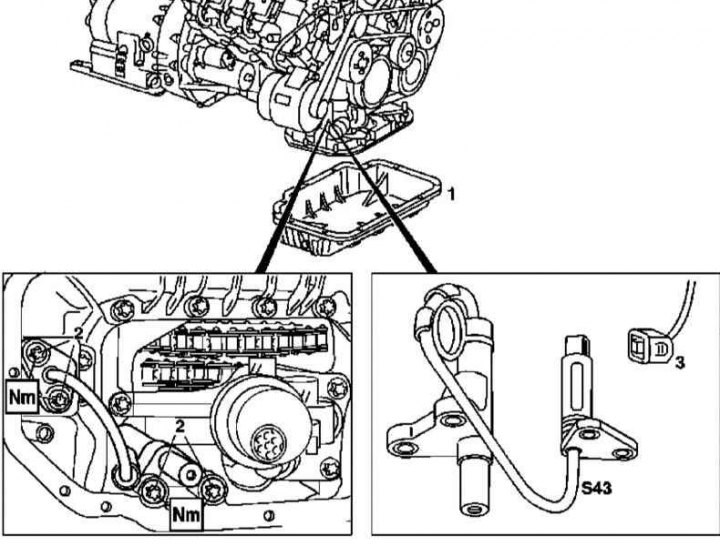
Details of installing the oil level sensor on engines of the 112 and 113 series
1. The details of installing the oil level sensor on engines of the 112 and 113 series are shown in the illustration, which includes all references in the text.
2. Remove the lower section of the oil pan (1) (see above).
3. Disconnect the connector (3) sensor wiring.
4. Turn out fixing bolts (2) and remove the oil level sensor (S43).
5. Installation is carried out in the reverse order.
Removal and installation of the oil pump
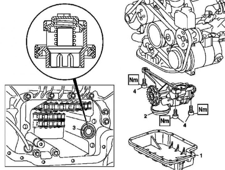
Oil pump installation details on 112 and 113 series engines
1. The installation details of the oil pump of the 112 and 113 series engines are shown in Ref. an illustration to which all references in the text refer.
2. Remove the lower section of the oil pan (1) (see above).
3. Remove the fixing screws (4).
4. Pull back the chain tensioner and remove the chain tensioner from the pump assembly drive sprocket.
5. Remove the oil pump (2).
6. Check the condition of the oil intake strainer, evaluate the correct fit of the control valve (3).
7. Fill pump assembly with fresh oil.
8. Installation is carried out in the reverse order.
Removal and installation of the pressure reducing valve of the oil pump
1. The installation details of the oil pump pressure relief valve components on 112 and 113 series engines are shown in the illustration above (see round inset), which includes all references in the text.
2. Remove the oil pump (see above).
3. Remove plug and replace relief valve assembly components.
Replacing the oil pump drive chain
1. The details of installing the oil pump drive on engines of the 112 and 113 series are shown in the illustration above, to which all references in the text refer.
2. Remove the lower section of the oil pan (1) (see above).
3. Remove the top section of the pallet (see above).
4. Remove the oil pump assembly (2) (see above).
5. Using a special tool, dismember the pump drive chain and remove it from the engine.
6. Remove the oil pump drive sprocket (25).
7. Installation is carried out in the reverse order - use a special tool to articulate the chain.
Removal and installation of oil sprayers
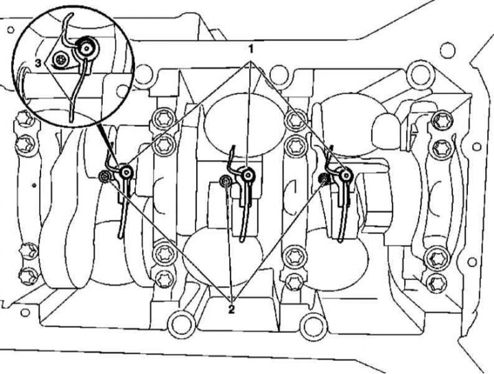
Details of installing oil sprayers on engines series 112 and 113
1. Details of the installation of oil sprayers on engines of the 112 and 113 series are shown in Ref. an illustration to which all references in the text refer.
2. Remove the lower and upper sections of the oil pan (see above).
3. Remove the oil pump (see above).
4. Turn out fixing bolts (2) and remove the oil diffusers (1), - turn the crankshaft slightly if necessary.
5. Check the patency of the oil flows, if necessary, clean them.
6. Installation is carried out in the reverse order - try not to deform the supply tubes (3) oil dispensers (1).