
Note. The camshaft sprocket bolts must be replaced without fail.
Camshaft adjuster
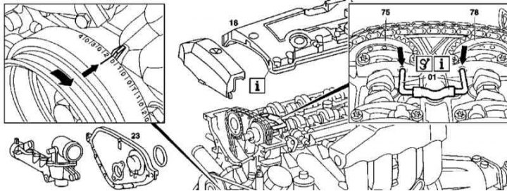
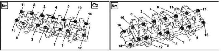
111 Series Engine Camshaft Adjuster Installation Details (1 of 2)
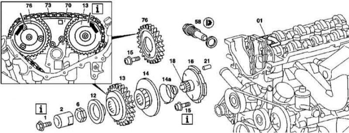
111 Series Engine Camshaft Adjuster Installation Details (2 of 2)
The details of installing the camshaft adjuster on the 111 series engine are shown in the illustrations, which include all references in the text.
Removing
1. Remove the cylinder head cover (18).
2. Remove the front cover (23) cylinder heads (see Section Removing and installing timing covers).
3. Turning the crankshaft in the normal direction, bring the piston of the first cylinder to the position of 20°after TDC and fix the camshafts (75 and 78) locking rods (01).
4. Mark the position of the gas distribution chain with a marker (73) regarding asterisks (76 and 13) camshafts.
5. Remove chain tensioner (58) (see Section Removal and installation of timing drive components).
6. Remove the sprocket (76) exhaust camshaft.
7. Remove the regulator from the intake camshaft.
Installation
1. Install the regulator in its original place.
2. Thread the chain and fit the sprocket onto the shaft trunnion (76).
3. Install the chain tensioner (58).
4. Remove the locking bars (01).
5. Turn the crankshaft twice in the normal direction, then check the basic setting of the camshafts (see Section Setting the basic position of the camshafts).
6. Install the front cover (23) cylinder heads (see Section Removing and installing timing covers).
7. Install the cylinder head cover (18).
Camshafts
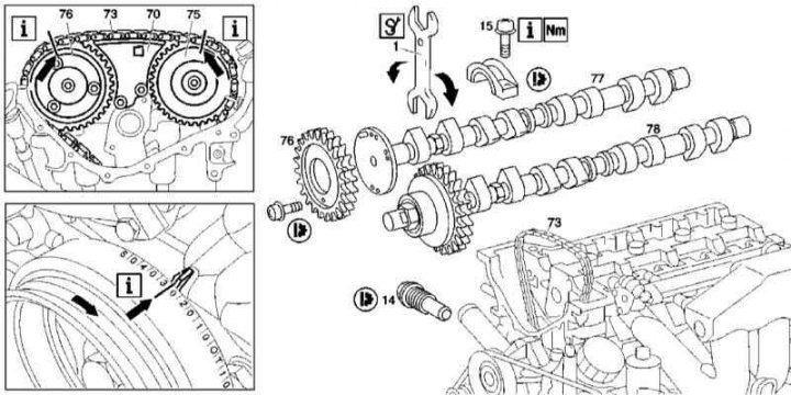
Details of installation of camshafts of the 111 series engine
1. The details of installing camshafts on 111 series engines are shown in the illustration, which includes all references in the text.
2. Remove the front cylinder head cover (see Section Removing and installing timing covers).
3. Having turned the crankshaft in the normal direction, bring the piston of the first cylinder to a position of 30°after TDC - in this position of the engine, the camshafts can be rotated without the risk of collision of valves with pistons.
4. Make sure the basic setting of the shafts is correct (see Section Setting the basic position of the camshafts), then mark the position of the gas distribution chain with a marker (73) regarding asterisks (75 and 76) camshafts.
5. Remove chain tensioner (14) (see Section Removal and installation of timing drive components).
6. Remove the sprocket (76) exhaust camshaft.
7. Raise the chain (73) and remove the star (75) intake camshaft.
8. With an open end wrench (1) expand the camshafts (77 and 78) in such a way as to maximally weaken the force developed by the valve springs, the cams should turn with their heels towards the pushers.
9. Mark covers of bearings of camshafts, then turn out fixing bolts and remove covers.
10. Carefully remove the camshafts from the cylinder head.
11. Installation is carried out in the reverse order - make sure that the bearing caps are correctly positioned.
М112/113 Camshaft bearing cap bridges
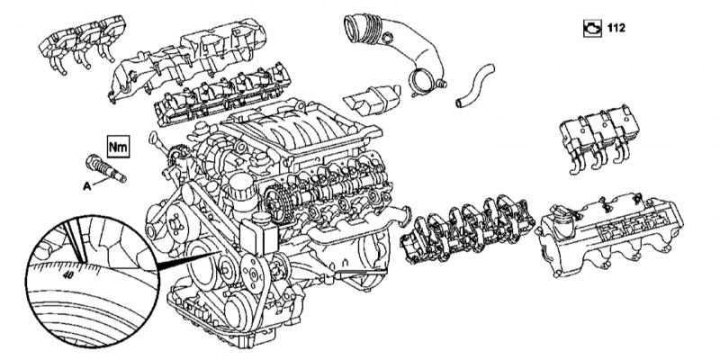
Details of installation of bridges of covers of bearings of camshafts of engines of series 112 and 113
The procedure for tightening the bolts of the bridges of the camshaft bearing caps on the 112 series engines
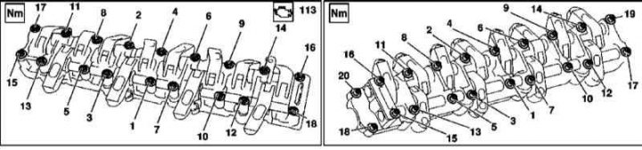
The order of tightening the bolts for fastening the bridges of the camshaft bearing caps on the 113 series engines
1. The installation details of the camshaft bearing caps on the 112 and 113 series engines are shown in the illustration, which includes all references in the text.
2. Remove the cylinder head covers.
3. Turning the crankshaft in the normal direction, bring the piston of the first cylinder to a position of 40°after TDC, in which there is no risk of the pistons colliding with the valves when turning the camshafts.
4. Remove chain tensioner (A) (see Section Removal and installation of timing drive components).
5. Tie the timing chain to the camshaft sprockets to prevent it from slipping.
6. In reverse order of illustrations, loosen and remove mounting bolts, then remove bearing cap bridges.
7. Installation is carried out in the reverse order - the tightening of the bolts for fastening the bridges of the camshaft bearing caps must be carried out strictly in a certain order.
Rocker axles
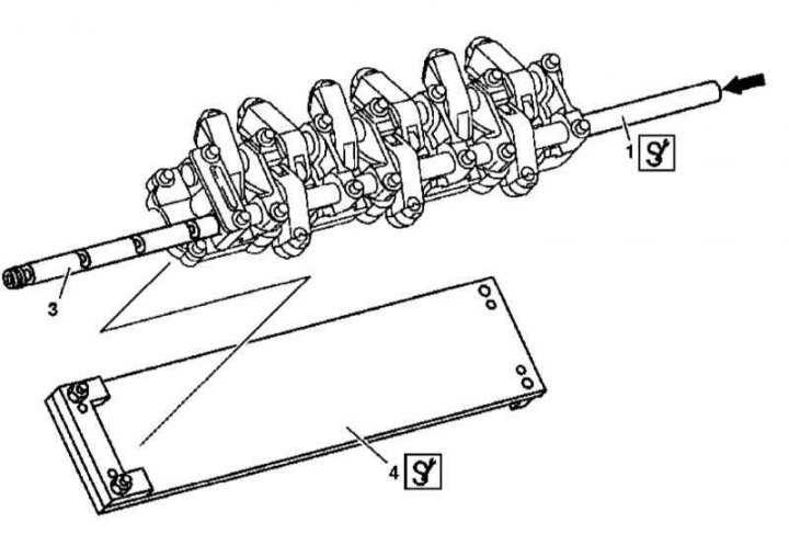
Details of installation of axes of rocker arms of a drive of valves on engines of series 112 and 113
Details of the installation of the axles of the rocker arms of the valve drive on engines of the 112 and 113 series are shown in the illustration, which includes all references in the text.
Removing
1. Remove the camshaft bearing cap bridge (see above).
2. Heat the bridge casting evenly to a temperature of approximately 150°C, - no more than 160°C!
3. Lay the bridge on the board (4) and remove the hollow axis of the rocker arms from it (1), gently tapping it from the opposite side through the drift (1) 15 mm in diameter.
4. Check up a condition of an axis and yokes, replace defective components.
Installation
1. Heat the axle evenly to 150°C, cool the rocker axle and gently tap it into the axle using guide shafts with a diameter of 16 (final assembly) or 18 (intake assembly) millimeters, - when tapping the axis, simultaneously remove the guide shaft, make sure that the rocker arms do not warp.
2. Align the rocker shaft by threading a pair of machine screws through the holes to the cover bridge.
3. Install bridge covers (see above).
Camshafts
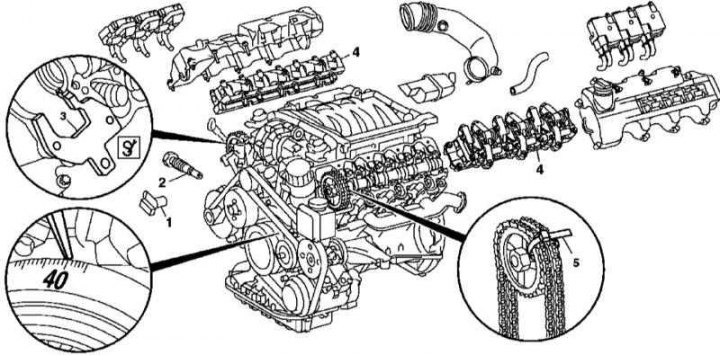
Details of installation of camshafts on engines of series 112 and 113
Details of the installation of camshafts on engines of the 112 and 113 series are shown in Ref. an illustration to which all references in the text refer.
Removing
1. Remove cylinder head covers.
2. Turning the crankshaft in the normal direction, bring the piston of the first cylinder to a position of 40°after TDC, in which there is no risk of pistons colliding with the valves when turning the camshafts.
3. Remove chain tensioner (2) (see Section Removal and installation of timing drive components).
4. Remove the Hall sensor (1).
5. Remove the camshaft sprocket after tying the gas distribution chain to it.
6. Remove the bearing cap bridge (4) (see above).
7. Remove the camshaft.
Installation
1. Install the camshaft in the cylinder head.
2. Install the bearing cap bridge (4) (see above).
3. Set the camshaft to the base position (see Section Setting the basic position of the camshafts).
4. Install the camshaft sprocket.
5. Install the Hall sensor (1)
6. Install chain tensioner (2) (see Section Removal and installation of timing drive components).
7. Check up correctness of combination of adjusting labels, then establish covers of heads of cylinders.