
- disconnect «mass» battery wire;
- drain the coolant from the cooling system;
- remove the grille and cross beam in order to provide better access to engine parts;
- cut the mounting clamps holding the engine wiring harness;
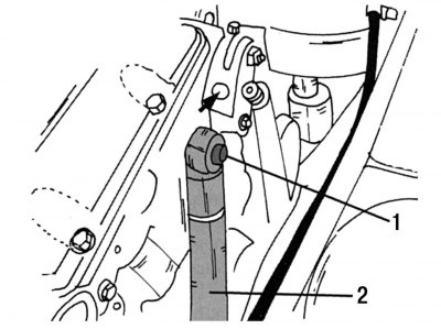
Pic. 23. Engine drive belt tensioner: 1 - bolt; 2 - damper of the belt tension mechanism
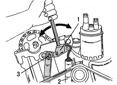
Pic. 24. Unloading the drive belt tensioner: 1 - damper; 2 - tension spring; 3 - fastening of the drive belt tensioner
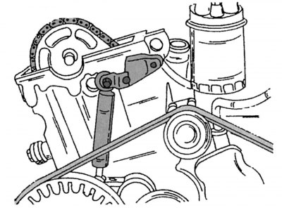
Pic. 25. Disconnecting the drive belt tension damper
- remove the drive belt from the end of the engine. On fig. 23 shows the tensioner for this belt. Bolt 1 holds the damper 2 of the belt tensioner. To remove the belt, unscrew the nut on the flange and insert the mandrel (diameter 12 mm and length 180 mm) into the hole in the spring tension lever marked with an arrow. Using this mandrel, move the tensioner to the left (pic. 24). Unload the hex bolt to the extent that the bolt can be unscrewed, and then slowly release the mandrel so that the tension spring moves towards the intake manifold and can be removed. Unscrew bolt 1 of damper 2 (see fig. 23) belt tensioner from the cylinder head (pic. 25) and remove fasteners (see also further description). After that, remove the V-ribbed belt;
- loosen the hose clamps of the cooling system hoses and disconnect the wire from the coolant temperature sensor;
- disconnect the engine control rod system;
- Disconnect the vacuum lines from the vacuum pump. Remove the hose and unscrew the union nut;
- tie the fuel lines with a suitable clamp and disconnect them from the fuel coarse filter, or remove the fuel filter and put it aside so that it does not interfere with work.
On a four-cylinder engine
Remove the high-pressure fuel lines of the first, second and third cylinders together with the fastening element, and the fuel line of the fourth cylinder without fastening.
On a five-cylinder engine
The high pressure pipes for cylinders 4 and 5 are held in place with two plastic clips. Remove the fuel return line from the No. 1 cylinder injector. To prevent the ingress of dirt, it is necessary to close its opening (e.g. with a bolt of suitable diameter);
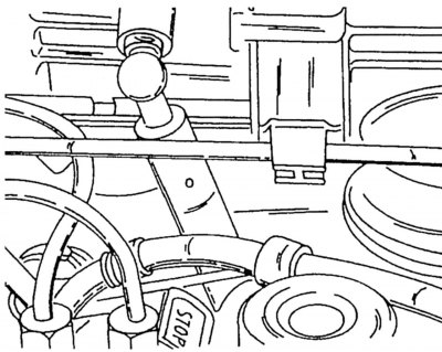
Pic. 26. Engine speed damper
- Disconnect the speed control damper from the intake manifold. It is located in the one shown in Fig. 26th place;
- disconnect the vacuum hose from the thermal valve;
- disconnect the wires from the glow plugs;
- disconnect the protective wiring box from the intake manifold and pull it forward;
- disconnect the fastening of the supply pipe of the heating system from the oil filter;
- disconnect the exhaust pipe flange from the exhaust manifold, as well as the clamp securing the exhaust pipe from the gearbox;
- remove the air duct connecting the air filter to the intake manifold;
- remove the intake manifold;
- remove the cylinder head cover. It is secured with six bolts on the top side of the engine. First remove the crankcase ventilation hose. On vehicles with automatic transmission, you must first disconnect the fuel control rod, which passes over the cylinder head cover;
- remove the viscous coupling bolted to the front side of the engine (the viscous coupling must not be placed on the impeller, it can only be placed on its side);
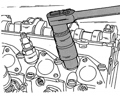
Pic. 27. Removing the fuel injection nozzle
- unscrew the fuel injection nozzles (pic. 27) and remove the sealing rings under them;
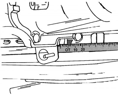
Pic. 28. The location of the marks when the piston of the first cylinder is at TDC
- crank the engine until the piston of the first cylinder is set to TDC, for this it is necessary to combine the alignment marks shown in fig. 28. You can turn the engine using a 27 mm interchangeable socket head mounted on the belt pulley nut and a ratchet. The crankshaft should be turned only in the direction of working rotation;
- remove chain tensioner (see the relevant subsection.). Unscrew the tensioner nut using a large hexagon. This nut is located above the water pump and thermostat cover;
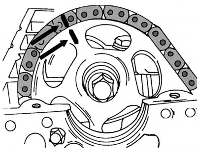
Pic. 29. Marking the position of the piston of the first cylinder at TDC
- the camshaft drive sprocket and the drive chain should be marked relative to each other. To do this, apply two strips of paint on the camshaft drive sprocket and on the drive chain, as shown in fig. 29;
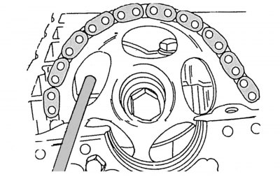
Pic. 30. Camshaft drive sprocket lock
- Remove the camshaft drive sprocket bolt. To prevent the camshaft from turning, block the camshaft sprocket with a large screwdriver or bolt, as shown in fig. thirty;
- Carefully remove the sprocket from the camshaft without allowing the drive chain to disengage from the crankshaft sprocket. This means that the chain must be kept constantly taut and properly tied;
- dismantle the camshaft, as described in subsection. 2.12.6. Uniformly unscrew the fixing bolts of the bearing caps;
- remove the chain guide from the cylinder head (subsection 2.12.4);
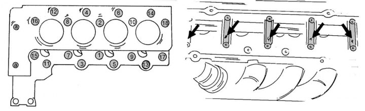
Pic. 31. The sequence of tightening the cylinder head bolts on a 2.3 liter engine
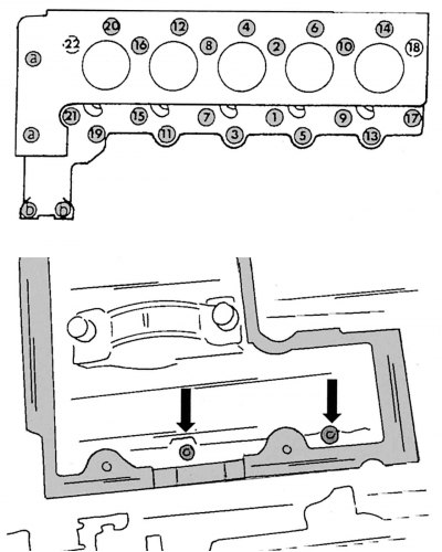
Pic. 32. The sequence of tightening the bolts of the cylinder head on a 2.9 liter engine
- now you can unscrew the cylinder head bolts. To prevent deformation of the head, its bolts should be unscrewed in the reverse order shown in fig. 31 and 32. To unscrew these bolts, you will need a so-called polygonal socket wrench. In the Mercedes-Benz specification, it is listed under the number 601 589 00 10 00. Using a conventional hex socket wrench can damage the bolt heads. Don't forget to remove the two small bolts in the chain case, which are shown at the bottom of fig. 32. These bolts are often overlooked. Immediately after all bolts have been loosened, their length must be measured from the lower edge of the bolt head to the end of the threaded part in order to determine the degree of their elongation. If the measurement results show that the bolt lengths, depending on the installation location, exceed 83.6; 105.6 and 118.5 mm, then these bolts must be replaced with new ones, the dimensions of which are 80; 102 and 115 mm. Tighten the bolts in reverse order;
- in the upper part of the chain housing, unscrew the two M8 bolts with heads for internal hexagon (shown at the bottom of Fig. 32). Insert hex key number 8 mm. In order to get close to these bolts, you must use the extension for the above key;
Note. We recommend that before unscrewing the bolts, mark them according to the numbering in fig. 31 for their correct subsequent installation: they are of different lengths, as some of them fix the camshaft bearing housings together with the cylinder head. They are shown by arrows in Fig. 32.
- remove the cylinder head. To facilitate this work, you can use the lifting device, securing the head to the lifting eyes;
- after removing the cylinder head, thoroughly clean the mating surfaces of the head and cylinder block. If necessary, repair the cylinder head in accordance with the instructions in subsection. 2.4.3;
- if it is necessary to replace only the gasket, the head must be installed on the engine;
- put a new cylinder head gasket on the connector surface;
- install the cylinder head, making sure that the guide bushings are in place. They are located on the same side;
- lubricate the threaded part and the contact points of the cylinder head bolts with engine oil. This is done after measuring the length of all bolts and replacing over-stretched bolts.
The installation and initial tightening of the bolts with a torque of 15 Nm must be carried out in the sequence shown in fig. 31 and 32. Then, in the same sequence, all the bolts are pulled with a torque of 35 Nm, after which a pause of 10 minutes must be maintained. Cylinder head fixing bolts have different lengths, so they must be installed in strict accordance with the marking and length.
After a sustained pause, tighten each bolt by 90°in the same sequence. It is not necessary to use a torque wrench to perform this work.
After that, it is necessary to tighten all the cylinder head bolts again by 90°, starting with bolt 1, taking into account the indicated sequence.
The two M8 hexagon head bolts shown at the bottom of fig. 32 must be tightened to 25 Nm. When a certain mileage of this vehicle is reached, subsequent broaching of the cylinder head fasteners is no longer necessary. A similar requirement existed previously for other types of vehicles.
Note. The design of the cylinder head can be upgraded. For this reason, you should not purchase used cylinder heads until you are sure that it fully matches the one installed on your car.
- install the chain guide on the cylinder head;
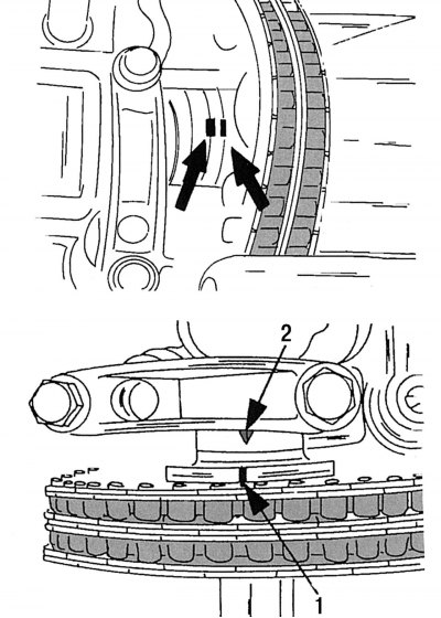
Pic. 33. Location of the camshaft guide pin (up). The location of the alignment marks corresponding to the position of the piston of the first cylinder at TDC (at the bottom): 1 - mark on the camshaft sprocket; 2 - mark on the cover of the first camshaft bearing
- put the drive sprocket on the camshaft together with the chain
- yu, paying attention to the fact that the marks made with paint are located on the same line (see fig. 29), and the shaft seat pin coincided with the hole in the sprocket. On the top of Fig. 33 shows where to check the engagement of the landing pin;
- tighten the camshaft drive sprocket mounting bolt to 45 Nm, holding it from turning with a large screwdriver or bolt, as shown in fig. thirty;
- install the chain tensioner by tightening its mount to 80 Nm;
- check the coincidence of the marks on the camshaft in the position of the piston of the first cylinder located at TDC. There is a mark on the camshaft, which, when the piston of the first cylinder is at TDC, should be against the cast arrow on the bearing cap. This arrangement of labels is shown at the bottom of fig. 33;
- connect the electrical wiring to the glow plugs;
- install the intake manifold;
- connect the fuel lines to the injectors;
- connect the exhaust pipe to the exhaust manifold;
- install the fuel filter and connect the fuel lines to it;
- install the drive belt tensioner, performing all operations in the reverse order of disassembly;
- install the cylinder head cover;
- connect the wire to the temperature sensor to output readings to the instrument cluster.
Perform all other work in the reverse order of removal.