



Contents: Removal ↡ Installation ↡
Note: Since this job requires some experience, only the basics required for an experienced mechanic are described.
Removal
1. Remove the air filter (2), depending on the engine model, together with the actuator for the circulation flap.
2. Remove the top engine cover (7/11).
3. Remove the cylinder head cover, refer to the relevant section.
4. Remove the air intake.
5. Models with AT: Disconnect the vacuum pipe at the electric vacuum pump. At the same time, squeeze both clamps of the lock and pull out the pipe. Disconnect the outlet pipe from the vacuum pipe.
6. Remove the EGR pipe clamp from the holder. Remove the changeover valve from the holder. At the same time, disconnect the two vacuum lines from the valve. Then disconnect the holder from the intake manifold.
7. Models with AT: Remove the transmission oil level indicator guide tube near the eye.
8. Remove the fuel distribution line with injectors.
9. Loosen the mounting bolts and remove the intake manifold from the cylinder head. Disconnect the vacuum hose of the recirculation valve. Move the intake manifold away from the cylinder head and secure it with the attached wires in the engine compartment.
10. Remove the crankcase ventilation pipe from the cylinder head.
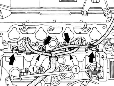
11. Disconnect the engine ventilation hoses (1) under the flange connection of the intake manifold and the cylinder head.
12. Remove the compressor drive V-belt, refer to the relevant section.
13. Remove the suction and discharge pipes of the compressor.
14. Remove the compressor.
15. Raise and place the vehicle on stands. Remove the engine compartment trim from below.
16. Drain the coolant, refer to Section Coolant Replacement - General Notes.
17. Disconnect the exhaust pipe from the exhaust manifold. Disconnect the pipe holder at the gearbox. Lower the exhaust system slightly and secure it with wire or cable connector.
18. Remove the EGR pipe from the cylinder block. Remove the EGR pipe holders on the right and left rear of the cylinder head.
19. Remove the heater coolant hose. To do this, press the clamp until it locks. Then remove the coolant line.
20. Set the piston of the first cylinder to the 20° after TDC position. To do this, turn the crankshaft by the pulley in the direction of engine rotation so that the 20° mark on the pulley coincides with the mark on the timing mechanism housing cover. In this position, the cams of the first cylinder of the intake camshaft and the exhaust camshaft should be at an upward angle.
21. Remove the thermostat housing, refer to Section Removal and installation the thermostat.
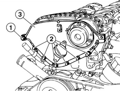
22. Remove the front cover (3). To do this, unscrew the 2 mounting bolts (1) on both sides of the front cover (3). The bolts have a thread diameter of 8 mm, in addition, there are guide bushings at the back of the cover. Unscrew the bolts (2) (thread diameter 6 mm) and remove the cover (3). Note the presence of a mating ring between the cover and the cylinder head. Clean the mating surfaces.
23. Mark the camshaft gears with paint in relation to the chain.
24. Remove the chain tensioner, refer to the relevant section.
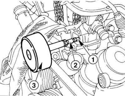
25. Remove the upper sliding guide. To do this, pull out the guide pin (1) by the thread using an impact puller (2) or some other suitable tool. To do this, ensure that the load slides relative to the stop.
26. Remove the exhaust camshaft gear. When unscrewing the bolts, hold the camshaft from turning by the hexagon.
27. Unscrew the bolts securing the intake camshaft bearing cover. Unscrew the bolts in several stages. Place the bolts so that they can be installed in their original places.
28. Remove the intake camshaft drive chain from the sprocket.
29. Remove the intake camshaft.
30. Remove the left guide pin.
31. Loosen the mounting bolts and remove the timing case cover from the cylinder head.
32. Loosen the cylinder head cover mounting bolts on a cold engine in the reverse order of their fastening, then unscrew the bolts.
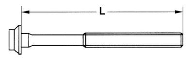
33. Measure the length of the M12 cylinder head bolts. The length of the new bolts is L = 102 mm. After each tightening, the length of the bolts increases. If the length is 106 mm or more, the bolts must be replaced. In this case, it is recommended to use only new bolts.
34. Using an assistant, remove the cylinder head.
Installation
Installation is performed in the reverse order of removal. The following must be observed:
1. Clean the contact surface of the cylinder head and cylinder block and check for cracks and unevenness. Clean the threaded holes.
2. Install the new sealing gasket in place.
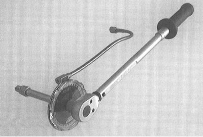
3. Install the cylinder head so that the guide bushings in the cylinder block enter the holes in the cylinder head. When installing the cylinder head, pay attention to the position of the guides.
Caution! The cylinder head bolts must be tightened with particular care. Before tightening, the accuracy of the torque wrench must be checked. To facilitate tightening the bolts to a given angle, an angle washer, such as HAZET 6690, can be used. To avoid loading the torque wrench with a large torque, the angle washer must be used together with a rigid wrench.
Note: If you do not have a corner washer, estimate the key angle by placing a rigid key so that the handle of the key is parallel to the engine, and turning the key one time so that the handle is perpendicular to the engine.
Technical data of the cylinder head are given in the Specifications.
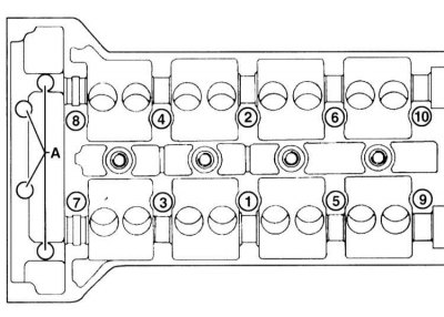
4. Lubricate the threads and bearing surface of the cylinder head bolt heads with oil and tighten in the established sequence from 1 to 10, first until they fit against the cylinder head, and then to the torques specified in the Specifications:
5. Lightly oil the bearing surfaces of the heads of the new cylinder head to timing case cover bolts (A) and install the bolts. Tighten the bolts to the specified torque.
6. Apply sealant "Omnifit FD 3041" before installing the guide pin. Secure the guide from above with a torque of 10 Nm.
7. Install the intake camshaft. Lubricate the compensating elements and bearing locations. Position the shaft so that the cams of the first cylinder are at an upward angle.
Note: When the engine is in long-term operation, check the axial clearance of the camshaft in the mounting bearing. Check the clearance of the camshafts, adjust if necessary.
8. Install the intake camshaft in its original place and tighten the mounting bolts evenly (risk of shaft damage). The camshaft bearings are numbered 1 to 10, starting from the intake camshaft side. Secure the bearing cap in several steps, one turn at a time, and finally tighten to 21 Nm.
9. Tighten the exhaust camshaft gear mounting bolts with new bolts to a torque of 20 Nm. Then tighten the bolts by an additional 60°.
10. Lubricate the mating surfaces of the front cover (3) on the cylinder head with a sealant, for example, "Omnifit FD 3041".
11. Insert the guide bushings for the two bolts (1) into the rear of the cover (thread diameter 8 mm). Install a new coolant sealing ring and replace the cap.
12. Tighten the bolts (1) on both sides to a torque of 25 Nm, the bolts (2) (thread diameter 6 mm) torque of 10Nm.
13. Before installation, check the heater coolant hose for damage, replace the hoses if necessary. Replace the sealing ring on the coolant supply.
14. Secure the EGR pipe with new sealing rings to the cylinder block.
15. Secure the exhaust pipe to the exhaust manifold with new bolts to a torque of 20 Nm.
Attention! Replace the rivet nuts in the manifold. To do this, screw the auxiliary bolt into the rivet nut by hand and knock out the rivet nut by hitting the bolt head. Pull in a new rivet nut with a bolt under the caulking and tighten to a torque of 30 Nm.
16. Secure the exhaust pipe holder to the gearbox with a torque of 20 Nm.

17. Secure the intake manifold (2) with new sealing gaskets (1) to the cylinder head with a torque of 20 Nm.
Caution: Pre-clean mating surfaces.
18. Reinstall the air intake, checking the sealing ring. Replace the ring if necessary.