
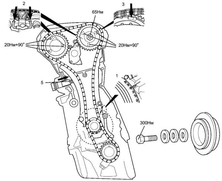
Timing chain drive diagram (timing) and steps of the valve timing setting procedure. Inline petrol engine 111.
Special tools:
- Camshaft locking tool - No. 111589031500.
- Camshaft key - No. 111589014000.
- Pulley / crankshaft hub puller - No. 000589883300.
- Crankshaft sprocket puller - No. 615589013300.
- Flywheel locking tool - No. 601589024000.
- Bolts for fixing the flywheel blocker - M6 x 90 mm.
- Devices for fixing the chain on the camshaft sprockets - No. 111589196100.
- Chain maintenance tool kit - No. 602589024000.
- Timing chain separator (element 1) - № 602589023300.
- Timing chain separator (element 2) - № 602589056300.
- Timing chain separator (element 3) - № 602589056301.
- Attachment for docking chain links - No. 602589003900.
- A set of dies for joining chain links - No. 112589096300.
- Tool box - No. 602589009800.
- Viscous clutch pulley holder (type 1) - № 119589024000.
- Viscous clutch pulley holder (type 2) - № 120589020100.
- The key for fixing the viscous coupling is No. 111589020100.
General Precautions
1. Disconnect the negative cable from the battery.
2. Turn out spark plugs for the purpose of simplification of cranking of the engine.
3. Unless otherwise noted, turn the engine in the normal direction only.
4. Familiarize yourself with the torque requirements for threaded connections.
5. If equipped, mark the position of the CKP sensor before removing it.
6. Do not turn the crankshaft using camshaft sprockets or other devices.
7. Do not turn the crankshaft and camshafts with the timing chain removed.
Valve Timing Procedures
Note. The timing chain can be replaced without removing the engine. Using the tools listed below, the new chain can be connected to the old chain, draped over the sprockets and riveted.
The viscous coupling nut has a left hand thread.
The screws securing the intake camshaft adjuster and the exhaust sprocket [9] must be replaced without fail.
1. Bring the piston of the first cylinder [1] to position 20°after TDC.
2. Make sure that the cams of the first cylinder valves of both camshafts are turned with the working ledges up.
3. Install locking devices [2] on the camshafts.
Note. If necessary, slightly correct the position of the crankshaft within the allowable ranges (20 ÷ 30°after TDC when the intake shaft is blocked and 25 ÷ 35°after TDC when the exhaust shaft is blocked) in order to facilitate the installation of blockers. Remember that turning the camshaft sprocket one tooth will move the crankshaft by approximately 20°.
4. On engines with intake camshaft adjustment, make sure that the regulator tabs remain in position during chain replacement «slowdown» [3].
Attention! Improper assembly may result in internal damage to the engine due to the impact of the valves on the piston crowns!
5. Loosen the tensioner nut [4] one turn and remove the tensioner assembly from the engine before proceeding with the repair procedures.
6. Loosen the tensioner spring nut [4], remove the pin [5] and spring [6], then press the plunger [7] in the tensioner housing [8] in the direction indicated by the arrow. Check the condition of the tensioner components, replace the defective elements.
7. Install the tensioner on the engine and tighten its fasteners with the required force (80Nm). Fit the plunger [7], spring [6] and pin [5] into the body [8]. Fit the nut [4] and tighten it to 40Nm.
8. Lubricate the crankshaft pulley center bolt and washer. Screw in the bolt and tighten it to the required torque [10].