
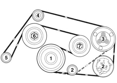
V-belt laying diagram. Engine 112
1 - Crankshaft; 2 - Deflecting roller 1 or compressor; 3 - Power steering pump; 4 - Deflecting roller; 2, 5 - Generator; 6 - Coolant pump; 7 - Tension roller
Removing
1. Loosen the V-belt tension.
2. Version 1: Place a Torx key on the central screw of the tensioner.
3. Execution 2: Place a wrench on the hexagon on top of the tension roller.
4. Tilt the tensioner counterclockwise and secure with a drift or a 5 mm diameter locking pin. To do this, insert the locking pin through the hole in the tensioner.
Installation
1. Put on the V-belt, starting with the tension roller. Next, put on the belt in accordance with the numbering shown in the figure.
2. Slightly turn the tension roller counterclockwise and remove the locking pin. Then slowly turn the idler pulley clockwise, making sure that the belt is correctly positioned on the pulleys.