
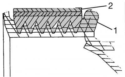
Pic. 140. Installing the V-ribbed belt on the pulley: 1 - pulley; 2 - V-ribbed belt
The coolant pump and alternator are driven by a single V-ribbed belt, which is mounted on a pulley, as shown in fig. 140.
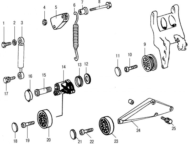
Pic. 141. The device of the tension mechanism (for 2.9 l engine): 1 - M8 bolt for fastening the damper to the cylinder head; 2 - washer; 3 - shock absorber; 4 — a nut of fastening of the lever of a spring to a head of the block; 5 - spring lever; 6 - spring; 7 - spacer sleeve; 8 — a bolt of fastening of a spring; 9 - belt tension roller; 10 — a bolt of fastening of a tension roller on an arm of the generator; 11 - plug fastening the roller; 12 - washer; 13 - sealing ring between the tension lever and the cover of the camshaft drive mechanism; 14 - tension roller lever; 15 - adjusting pin of the tension lever on the cover of the camshaft drive mechanism; 16 - tension roller cover; 17 - M7 bolt for fastening the damper to the tension lever; 18 - cap fastening the tension roller; 19 — a bolt of fastening of a tension roller on the lever; 20 - belt tension roller; 21 - cap fastening the tension roller; 22 - M8 bolt; 23 - guide roller; 24 - guide roller mounting bracket; 25 — a bolt of fastening of an arm to the block of cylinders
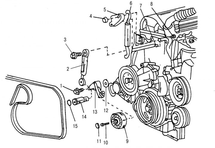
Pic. 142. The device of the tensioning mechanism of the belt drive (the damper can be removed separately without dismantling other parts): 1 - bolt; 2 - damper; 3 - bolt; 4 - nut; 5 - spring lever; 6 - spring; 7 - bolt; 8 - bolt; 9 - belt tension roller; 10 - bolt; 11 - plug; 12 - washer; 13 - tension lever; 14 - bolt; 15 - plug
The belt is in tension due to the tension roller held by the spring. The installed damper prevents vibration of the belt. On fig. 141 shows the individual parts of the belt drive tensioner. Tension rollers are not interchangeable for various models. In the basic configuration, without installed additional units, the tension roller has the same groove width as other pulleys. In other versions, the surface of the roller is smooth. This must be taken into account when replacing. On fig. 142 shows the entire tensioner. To access it, the front of the engine must first be disassembled.
The belt drive must be checked every 20,000 km. To do this, put a chalk mark on the belt in an accessible place. Turn the engine over with the starter at least one revolution. To prevent the engine from starting, press the fuel pump shut-off lever with a screwdriver. While turning the engine over with the starter, inspect the entire length of the belt until a mark appears. Cracked, frayed or burnt areas indicate the need to replace it.
To remove and install the drive belt, perform the following steps:
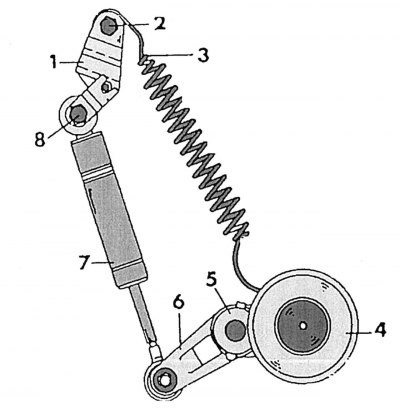
Pic. 143. Details of the tensioning mechanism of the drive belt: 1 - tension lever; 2 - nut; 3 - return spring; 4 - tension roller; 5 - plug; 6 - tension roller lever; 7 - damper; 8 - damper top mount
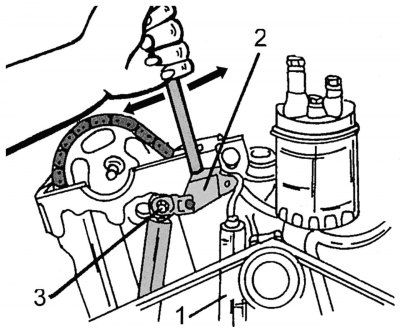
Pic. 144. The weakening of the action of the tensioning mechanism of the belt drive: 1 - spring; 2 - shock absorber; 3 - fastening of the tension mechanism
- loosen the tension lever nut 1 (pic. 143) and insert the rod into the tensioner lever as shown in fig. 144. As a rod, you can use, for example, a metal bar with a diameter of 12 mm and a length of 180 mm;
- lightly press the rod to the left side to wring out the bolt;
- now slightly press the rod to the right, loosening the tension spring;
- push down the tension roller so that the belt can be removed.
Belt installation is carried out in the reverse order. First, pass the belt through the tension roller, then put it on all the pulleys in sequence. Lastly, the belt is put on the coolant pump pulley. If the work is carried out correctly, the belt is installed in a taut state.
Removal and installation of the belt tension mechanism is performed in the following sequence:
- release the front of the engine for access to the details of the mechanism;
- remove the drive belt as described above;
- remove the tension lever 5 (see fig. 142) springs and spring 6. When assembling, install the spring with the colored mark up;
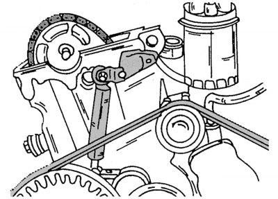
Pic. 145. Location damper tensioner (unscrew only from the cylinder head)
- unscrew the damper from the block head (pic. 145);
- remove plug 15 (see fig. 142) and unscrew the bolt 1 of the tension lever 13. When unscrewing the bolt 14, press the tension lever in the direction against the plug. Thoroughly clean the thread of bolt 1 before refitting. Apply sealant to the thread of bolt 1. Before installing the tension lever on bolt 1, lubricate the space between the bushings of the lever bearing;
- remove the tension lever 13 together with the damper 2 from the tension roller 9. In this case, do not lose the washer 12;
- disconnect the damper 2 from the tension lever 13. When replacing the damper, release the air by pressing the rod several times. The damper is installed with the stem down, as shown in fig. 142;
- remove the plug 11, unscrew the bolt 10 and remove the tension roller 9 from the tension lever 13.
Assembly is carried out in the reverse order, taking into account the following tightening torques (N·m):
- tension roller to the tension lever - 30;
- tension lever - 100-110;
- damper to the block head - 21;
- damper to the tension lever - 20;
- tension lever to the head of the block - 21.