



Repair of diesel engines of the car Mercedes Vito 2 (W639)

General information
The OM 646 diesel engine is a modernization of the OM 611 engine, which was widely used in previous Mercedes-Benz models and was installed in passenger cars, off-road...
The OM 646 diesel engine is a modernization of the OM 611 engine, which was widely used in previous Mercedes-Benz models and was installed in passenger cars, off-road...

Vehicle option codes
Options Option Contents MC1 Diesel engine OM646 DE 22LA, 65 kW (83 hp), at 3800 rpm MC2 Diesel engine OM646 DE 22LA, 80 kW (109 hp), at 3800 rpm MSZ Diesel engine OM646...
Options Option Contents MC1 Diesel engine OM646 DE 22LA, 65 kW (83 hp), at 3800 rpm MC2 Diesel engine OM646 DE 22LA, 80 kW (109 hp), at 3800 rpm MSZ Diesel engine OM646...

Engine specifications
Traction and speed characteristics VN 2.002 Design features and characteristics of engines A significant design difference is the use of a mechanical two-shaft engine...
Traction and speed characteristics VN 2.002 Design features and characteristics of engines A significant design difference is the use of a mechanical two-shaft engine...

Removal and installation of the power unit
VN 2.003 1. Left engine mount 2. Right support engine support 3. Screw M8x130 mm for fastening the left support to the cylinder block, strength class 8.8 4. Screw for...
VN 2.003 1. Left engine mount 2. Right support engine support 3. Screw M8x130 mm for fastening the left support to the cylinder block, strength class 8.8 4. Screw for...

Units and assemblies in the front part of the engine
VN 2. 039 1. Vacuum pump 2. Fuel injection pump 3. Poly V-belt 4. Coolant pump 5. Front cylinder head cover 6. Poly V-belt tensioner 7. Screw cap of oil filter 8. Power...
VN 2. 039 1. Vacuum pump 2. Fuel injection pump 3. Poly V-belt 4. Coolant pump 5. Front cylinder head cover 6. Poly V-belt tensioner 7. Screw cap of oil filter 8. Power...

Removal and installation of the cylinder head (CH)
1. Disconnect the negative battery cable. 2. Remove the air filter housing. 3. Drain the coolant. 4. Loosen the screw (1) securing the turbocharger to the lower part of...
1. Disconnect the negative battery cable. 2. Remove the air filter housing. 3. Drain the coolant. 4. Loosen the screw (1) securing the turbocharger to the lower part of...

Checking the relative position of the camshafts
30.1. Check the relative position of the camshafts. The holes (B) of the gears (1) and (2) must be opposite each other (see figure VN 2.047), The relative position of...
30.1. Check the relative position of the camshafts. The holes (B) of the gears (1) and (2) must be opposite each other (see figure VN 2.047), The relative position of...

Checking the relative position of the crankshaft and camshaft system
30.2. Check the relative position of the crankshaft and camshaft system. When setting the crankshaft to the TDC position of the piston of the first cylinder, the marks...
30.2. Check the relative position of the crankshaft and camshaft system. When setting the crankshaft to the TDC position of the piston of the first cylinder, the marks...
Cylinder head repair
Cylinder head repair consists of complete disassembly and inspection of the condition of the parts: cylinder head housings (cylinder head mating plane); valves (wear of...
Cylinder head repair consists of complete disassembly and inspection of the condition of the parts: cylinder head housings (cylinder head mating plane); valves (wear of...

Removal and installation valves
1. Place the cylinder head (7) on a flat surface. 2. Install the spring compressor (9) onto the cylinder head. 3. Using the tool (9), compress the valve springs so that...
1. Place the cylinder head (7) on a flat surface. 2. Install the spring compressor (9) onto the cylinder head. 3. Using the tool (9), compress the valve springs so that...


Valve guide bushings
If the gap in the bushing-valve pair is too high (usually the maximum permissible value is 0.1 mm). The normal gap in a new engine is 0.03-0.07 mm. VN 2.063 Maximum gap...
If the gap in the bushing-valve pair is too high (usually the maximum permissible value is 0.1 mm). The normal gap in a new engine is 0.03-0.07 mm. VN 2.063 Maximum gap...

Processing of cylinder head for installation of valve guide bushings
When replacing valve guide bushings, machining of the holes is performed with the camshaft housing installed. In this case, the base surface for processing is the...
When replacing valve guide bushings, machining of the holes is performed with the camshaft housing installed. In this case, the base surface for processing is the...

Checking hydraulic valve clearance compensators
Press the valve tappet (1), which includes the hydraulic clearance compensator, with a suitable tool (2) using normal hand force. When pressed in this way, all hydraulic...
Press the valve tappet (1), which includes the hydraulic clearance compensator, with a suitable tool (2) using normal hand force. When pressed in this way, all hydraulic...
Disassembly and repair of the lower part of the engine
To provide access to the crank mechanism parts, the following steps should be taken. Remove all components of the auxiliary drive belt tensioner. Remove the boat's oil...
To provide access to the crank mechanism parts, the following steps should be taken. Remove all components of the auxiliary drive belt tensioner. Remove the boat's oil...
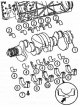
Removal and installation the crankshaft
1. Remove the connecting rod bearing caps. 2. Remove the main bearing caps. 3. Remove the crankshaft from the bed. 4. Remove the pistons with connecting rods as an...
1. Remove the connecting rod bearing caps. 2. Remove the main bearing caps. 3. Remove the crankshaft from the bed. 4. Remove the pistons with connecting rods as an...
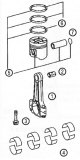
Connecting rod and piston group of parts (CRP) — composition
VN 2.068 1. Connecting rods (A 611 030 05 200) with subsequent replacement by (A 646 030 00 20.004) 2. Connecting rod upper head bushings (A 611 038 01 50) 3. Screws (A...
VN 2.068 1. Connecting rods (A 611 030 05 200) with subsequent replacement by (A 646 030 00 20.004) 2. Connecting rod upper head bushings (A 611 038 01 50) 3. Screws (A...

Crank mechanism (CRM) — composition
VN 2.069 1. Knee hall (A 646 031 07 01) subsequently replaced by (A646 031 04 01 +001 A108 991 00 67) As an option: (A 611 031 05 01 001 001 001) 1. Crankshaft (A 611...
VN 2.069 1. Knee hall (A 646 031 07 01) subsequently replaced by (A646 031 04 01 +001 A108 991 00 67) As an option: (A 611 031 05 01 001 001 001) 1. Crankshaft (A 611...

Checking and repairing connecting rods
Replacing the upper connecting rod head bushing To replace a worn bushing of the upper connecting rod head, it should be pressed out and a new one pressed in using a...
Replacing the upper connecting rod head bushing To replace a worn bushing of the upper connecting rod head, it should be pressed out and a new one pressed in using a...

Connecting pistons to connecting rods and installing them in the cylinder block
The connection of the pistons to the connecting rods is made using piston pins. The piston pins (6), installed in place, are secured with spring retaining rings...
The connection of the pistons to the connecting rods is made using piston pins. The piston pins (6), installed in place, are secured with spring retaining rings...

Measuring the piston protrusion above the parting plane of a new cylinder block
After replacing the pistons, connecting rods and machining the upper surface of the cylinder block, the amount of piston protrusion above the cylinder block should be...
After replacing the pistons, connecting rods and machining the upper surface of the cylinder block, the amount of piston protrusion above the cylinder block should be...

Front cylinder block cover
VN 2.092 1. Front cover (A 646 010 09 33) 2. Centering sleeve (A 611 997 00 10) 3. Screw plug 4. Sealing ring 5. Sealing ring 6. Screw M10x1 7. Sealing ring 8. Oil...
VN 2.092 1. Front cover (A 646 010 09 33) 2. Centering sleeve (A 611 997 00 10) 3. Screw plug 4. Sealing ring 5. Sealing ring 6. Screw M10x1 7. Sealing ring 8. Oil...

Installing the rear cylinder block cover
VN 2.094 2. Screws for fastening the rear cover to the cylinder block (8 Nm) 3. Screws for fastening the oil pan to the rear cover of the cylinder block. 1. Installation...
VN 2.094 2. Screws for fastening the rear cover to the cylinder block (8 Nm) 3. Screws for fastening the oil pan to the rear cover of the cylinder block. 1. Installation...

Installing an oil pump
VN 2.096 1. Tensioner shoe 2. Oil pump drive chain 3. Oil pump drive sprocket 4. Oil pump 5. Screws 6. Sealing ring
VN 2.096 1. Tensioner shoe 2. Oil pump drive chain 3. Oil pump drive sprocket 4. Oil pump 5. Screws 6. Sealing ring

Installing the flywheel
VN 2. 095 1. Flywheel 2. Washer 3. Screw 4. Pin 5. Crankshaft Installing the oil pan VN 2. 097 1. Holes for screws M6x20 (9 Nm) 2. Holes for screws M6x35 (9 Nm) 3. Holes...
VN 2. 095 1. Flywheel 2. Washer 3. Screw 4. Pin 5. Crankshaft Installing the oil pan VN 2. 097 1. Holes for screws M6x20 (9 Nm) 2. Holes for screws M6x35 (9 Nm) 3. Holes...
This section is available on: russian, bulgarian, belarusian, ukrainian, serbian, croatian, romanian, polish, slovak, hungarian
More similar sections for repairing other models
☛ Power unit: Engine repair car Mercedes W168 (1997-2004)
☛ Power unit: Engine device car Mercedes W123 (1976-1985)
☛ Power unit: Engine repair car Mercedes W463 (1999-2019)
☛ Power unit: 8-cylinder V8 engine car Mercedes W116 (1972-1980, petrol)
Link in different formats to this section
TEXTHTMLBB Code
- General information
- Maintenance
- Power unit
- Engines 602.984/985
- Engines 904.908/914/923/936
- Transmission
- Clutch
- Manual gearbox 711.613
- Manual gearbox 710.64/66
- Manual gearbox 715.051
- Automatic gearbox 723.345
- Power take-off box
- Chassis
- Front suspension
- Rear suspension
- Steering
- Brake system
- Body and electrical equipment
- Interior (internal elements)
- Exterior (external elements)
- Heater and air conditioner
- Electrical diagrams
- General information
- User manual
- Maintenance
- Diesel engine OM646
- Engine repair
- Cooling and lubrication system
- Power and exhaust system
- Transmission
- Clutch
- Car gearbox
- Chassis
- Front suspension
- Rear suspension
- Steering
- Brake system
- Body
- Body elements
- Electrical equipment
- Equipment and devices
- Security systems
- Electrical circuits
- General information
- User manual
- Maintenance
- Petrol engines 2.0 l
- Engine repair
- Lubrication system
- Cooling system
- Power and control system
- Petrol engines 2.8 l
- Engine repair
- Lubrication system
- Cooling system
- Power and control system
- Diesel engines 2.3 l
- Engine repair
- Cooling system
- Lubrication system
- Turbocharging and recycling
- Power and control system
- Diesel engines 2.2 l
- Engine repair
- Cooling system
- Lubrication system
- Turbocharging and recycling
- Power and control system
- Transmission
- Clutch
- Mechanical gearbox
- Automatic gearbox
- Chassis
- Front suspension and wheels
- Rear suspension
- Steering
- Brake system
- Body
- Exterior (external elements)
- Interior (internal elements)
- Electrical equipment
- Equipment and devices
- Heater and air conditioner
- Electrical circuits
- General information
- Introduction to the guide
- Maintenance
- Power unit
- Engine repair
- Lubrication system
- Cooling system
- Power and exhaust system
- Transmission
- Clutch
- Mechanical gearbox
- Automatic gearbox
- Front axle
- Rear axle and cardan
- Chassis
- Car suspension
- Steering
- Brake system
- Tires and wheels
- Electrical equipment
- Equipment and devices
- Headlights and lighting
- Power devices
- Electrical circuits