



2. Install the spring compressor (9) onto the cylinder head.
3. Using the tool (9), compress the valve springs so that the crackers (6) come out of the conical hole in the upper support (5) of the valve spring,
4. Using the magnetic rod (10), remove the crackers (6).
5. Remove the upper valve spring supports (S) and valve springs (4).
6. Using the valve seal pliers (11), remove the valve seals (3),
7. Remove the lower valve spring supports (2).
8. Lift the cylinder head (7) and remove the valves (1).
[Article borrowed from the web portal: mercedesman.ru]
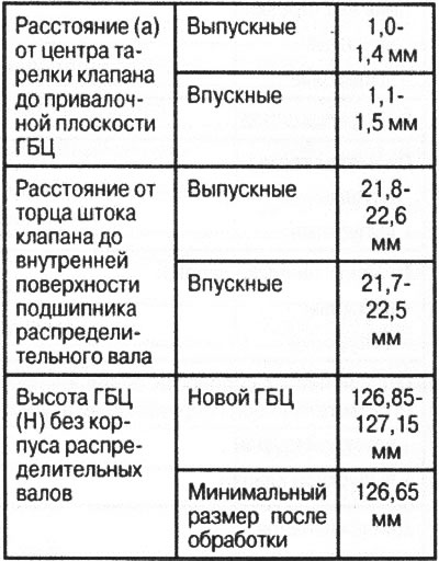
Cylinder head control dimensions
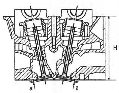
VN 2.059
a. Distance from valve plate to cylinder head bearing surface
H. Cylinder head height without camshaft housing
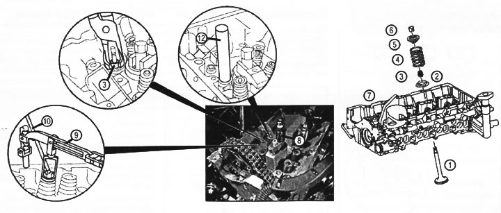
VN 2.060
Removing and installing valves
1. Inlet and outlet valves
2. Lower valve spring support
3. Valve sleeve
4. Valve spring
5. Upper valve spring support
6. Rusks
7. Cylinder head
8. Threaded mounting sleeve
9. Spring compressor
10. Magnetic rod
11. Tweezers for removing sebaceous valve caps
12. Mandrel
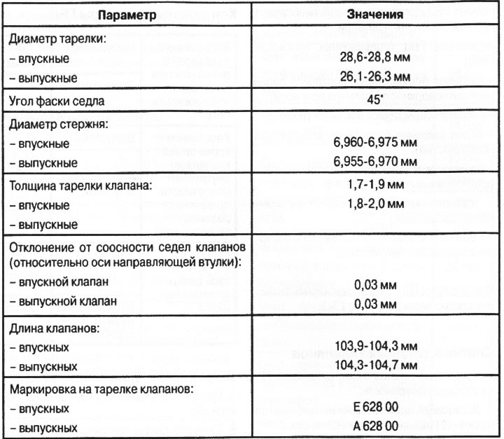
Control parameters of valves
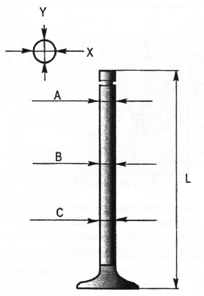
VN 2.061
Valve stem diameter: Intake: 6.960-6.975 mm, Exhaust: 6.955-6.970 mm
Length L of valves: Inlet: 103.9-104.3 mm, Exhaust: 104.3-104.7 mm
Install in reverse order. When installing the valve seals, lubricate them with oil and press them in using a mandrel (12) (see figure VN 2.060). To protect the valve seal oil scraper edge, a protective plastic cap should be installed on each valve.