
When installing the crankshaft to the TDC position of the piston of the first cylinder, the marks on the camshafts must be aligned with the marks on the camshaft bearing caps. A necessary condition for the reliability of the results of such a check is the installation of the movable part of the chain tensioner in the working position.
32. Remove the front cylinder head cover (see fig. VN 2.048).
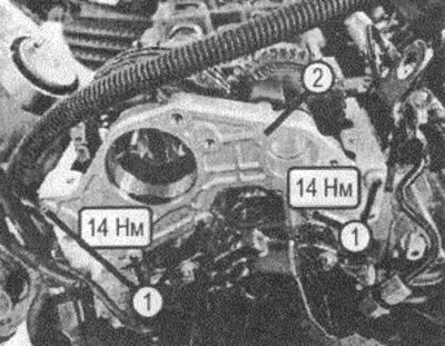
VN 2.048
1. Screws for securing the front cover to the cylinder head
2. Front cylinder head cover
33. Remove the intermediate gear of the injection pump drive (see fig. VN 2.049).
34. Remove the camshafts (1) and camshaft housing (2) (see fig. VN 2.050).
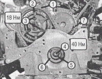
VN 2.049
1. Timing chain
2. Exhaust camshaft sprocket
3. Screws for fastening the exhaust camshaft sprocket
4. Screw for fastening the intermediate gear of the injection pump drive
5. Sleeve
6. Intermediate gear drive high pressure fuel pump
7. Pin fixing the position of the gear of the camshaft of the intake valves
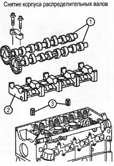
VN 2.050
1. Camshafts
2. Camshaft housing
3. Mounting sleeves
Removing
34.1. Remove the cylinder head cover (4) (see fig. VN 2.051).
34.2. Set piston cylinder number (1) at TDC. The engine should be rotated by the crankshaft clockwise. It is unacceptable to rotate the engine by the camshaft, as well as rotate it in the opposite direction.
When assembling, align the marks on the camshaft and bearing caps, vibration damper belt pulley (arrow).
34.3. Fix the camshaft (1) inlet valves with a retainer (3) (hole A). holes (IN) on the gears of the camshafts should be located opposite each other.
34.4. Remove front cover (6) cylinder heads.
Removal and installation of camshafts
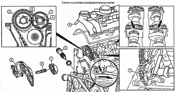
VN 2.051
1. Inlet camshaft
2. Camshaft exhaust valves
3. Intake camshaft lock
4. Cylinder head cover
5. Chain tensioner
6. Front cover
7. Chain guide shoe
8. Chain guide axle
A. Hole for installing the latch 3
B. Synchronizing holes, which are marks of the relative position of the involute gear pair (when properly installed, the mechanism must be aligned)
34.5 Disconnect the chain wheel (11) camshaft drive (2) exhaust valves and remove it together with a view to (see fig. VN 2.052). Hold the shaft with the key.
34.6. Remove bearing caps (13) camshafts. Loosen the fastening screws (12) bearing caps (13) evenly over several passes until tightening stresses are evenly relieved. Lids are labelled.
34.7. Remove the intake camshafts (1) and graduation (2) valves.
Installation
34.9. Install the exhaust camshaft (1) and intake camshaft (2). Align marks (IN) on the gears of the camshafts pairs and marks on the camshafts with marks on the bearing caps (see fig. VN 2.051).
34.10. Install the camshaft bearing caps (13) (see fig. VN 2.052), Install covers (13) in reverse order, screws (12) tighten sequentially, turning each screw one turn per pass. Lids are marked (see fig. VN 2.053): they are numbered sequentially from front to back, the intake camshaft covers are marked E1-E5 (E1-E6), graduation A1-A5 (A1 -Ab).
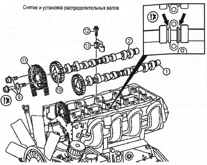
VN 2.052
1. Shaft of distributive inlet valves
2. Shaft of distributive final valves
9. Screw for fastening the sprocket to the drive gear of the involute gear that synchronizes the camshafts
10. Locating pin
11. Exhaust camshaft drive sprocket
12. Camshaft bearing cap screw
13. Camshaft bearing cap
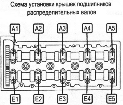
VN 2.053
Tightening torques for threaded connections
Screw for fastening the gear wheel to the camshaft - 18 Nm.
The screw of fastening of a cover of bearings - 9 Nm.
Bolt for fastening the guide to the intake camshaft - 50 Nm.
35. Loosen the screws (7) (see fig. VN 2.044).
36. Loosen the screws (8) (see fig. VN 2.044) cylinder head mountings in the sequence shown in fig. VN 2.054.
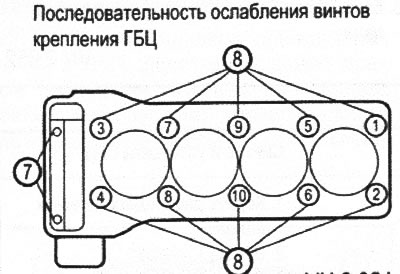
VN 2.054
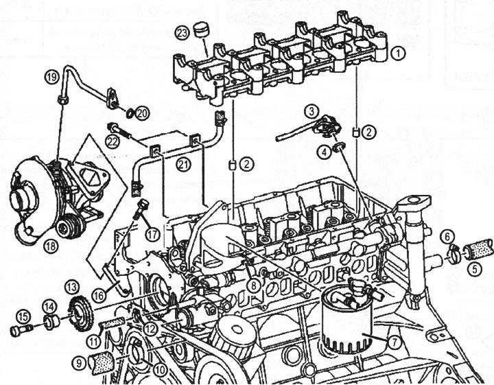
VN 2.055
Removal and installation of cylinder head
1. Camshaft housing
2. Sleeve
3. Fuel line
4. O-ring
5. Coolant hose
6. Collar
7. Fuel filter
8. Screw
9. Coolant hose
10. Collar
11. Coolant hose
12. Collar
13. Intermediate sprocket of injection pump drive
14. Sleeve
15. Screw
16. Sleeve
17. Screw
18. Turbocharger
19. Turbo fuel supply line
20. O-ring
21. Turbine coolant line
22. Screw
23. Hydraulic compensator
37. Remove the cylinder head by lightly tapping with a plastic mallet.
38. Install in reverse order. Before installation, check the suitability of the cylinder head screws for further use (see fig. VN 2.056).
Checking the length of the cylinder head screws
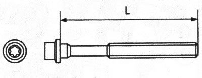
VN 2.056
Thread: M12
Length (L) new 102 mm
Maximum length (L) 104 mm
The sequence of an inhaling of screws of fastening of a cylinder head is shown in fig. VN 2.057. In this sequence, the screws should be tightened in each of the four stages.
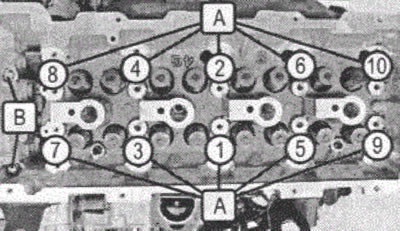
VN 2.057
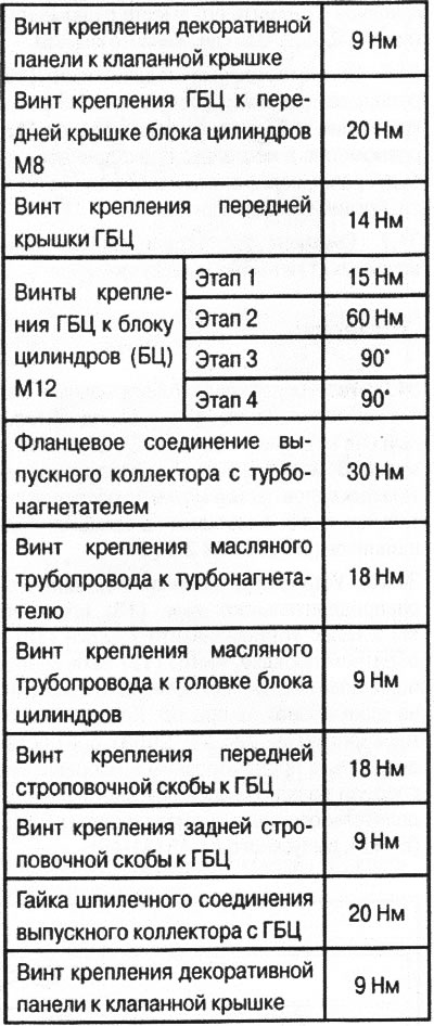
Tightening torques
Valve cover
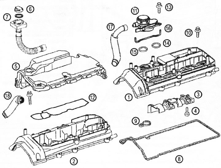
VN 2.058
1. Valve cover
2. Valve cover for engines with PR number (MF4)
3. Figured plate
4. M5 screw
5. Valve cover top panel
6. Oil filler cap
7. Cover gasket with an oil filler neck
8. Valve cover gasket
9. Gasket
10. Valve cover screw
11. Oil separator
12. Gasket
13. Screw for fastening the oil separator M6x30 mm
14. O-ring
15. O-ring
16. Oil separator gasket
17. Air duct between pressure control valve and air manifold
18. Air duct between pressure control valve and air manifold (MF4)